
User Manual


Project Overview Statement—Executive Summary
Confidential Page 4 4/8/2015
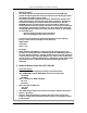
Connector P1 Pin description:
PIN1- PPM signal, TTL 5V
PIN2- Not connected,
PIN3- VCC In, 6-18VDC, 100mA
PIN4- GND
PIN5- for future use
Antenna connector:
SMA connector to attach a standard rubber duck 2.4GHz 50Ohm antenna.
Buttons
Button 1(ID)
Both Spectrum and Walkera modes:
when pressed upon power on a new unique ID is assigned to Tx.
Totally 4 billion combinations available. Procedure of the ID changing is
described in Functionality And Modes section below
Button 2(Bind)
In Spectrum mode:
When the module is powered on while the button is pressed a binding
procedure is initiated.
When pressed during operation the output power is reduced to xxmW for a
range check
In Walkera mode:
When pressed during operation the output power is reduced xxmW for a range
check
Functionality and Modes
Functionality at modes chosen by switches
1. Walkera mode (SW1 - ON)
Inputs and outputs:
SW2 provides channel mapping according to switch description
SW3..SW6 are ignored
SW7, SW8 change output power selection according to switches description
Button1 – ID change
Button2 – When pressed during operation the output power is reduced to
xxmW for a range check. When pressed during power on the button is ignored.
There is no binding procedure by button in Walkera Devo mode.
Buzzer – see Functionality
LED – see Functionality
Functionality
Power ON:
When powered up the module is waiting for valid PPM signal to be detected.
As soon as PPM signal is detected the buzzer generates three short