
User's Manual


Maps and Registers System Configuration Registers
122 SPARC/CPU−56T
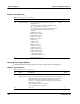
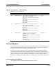
Address: 1FF.F160.0130
16
Table 32: Watchdog Timer Control Register
Bit
Name Description Default Access
4..0 WDOG LENGTH These bits are used to set the time−out for the
watchdog timer.
The tolerance of the time delay is 100ppm or +10
ms/−10 ms whichever is greater.
The values given below indicate: Time after which
reset is initiated/Time after which interrupt is
triggered
00000
2
: 125 ms/62 ms
00010
2
: 250 ms/125 ms
00100
2
: 500 ms/250ms
00110
2
: 1 s/500 ms
01000
2
: 2.5 s/1.25ms
01010
2
: 5s/3 s
01100
2
: 10 s/8 s
01110
2
: 30 s/25 s
10000
2
: 1 min/50 s
10010
2
: 3 min/2 min
10100
2
: 5 min/4 min
10110
2
: 10 min/8 min
11000
2
: 20 min/18 min
11010
2
: 30 min/25 min
11100
2
: 60 min/50 min
11111
2
: Watchdog timer off
01000
2
r/w
7..5 aa These bits are always zero. aa aa
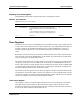
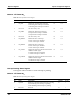
Watchdog Timer Trigger Register
The Watchdog Timer Trigger register is used to trigger the watchdog timer.
Address: 1FF.F160.0131
16
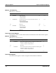
Table 33: Watchdog Timer Trigger Register
Bit
Name Description Access
2..0 1 Reserved w
3 WDOG TRIG This bit is used to trigger the watchdog timer. If the watchdog is
enabled through the switch SW1−3, the software must set this bit
within the time period configured in the Watchdog Control
register. If a watchdog interrupt is pending, it will be cleared by
triggering the watchdog.a
0: The watchdog timer is not triggered.
1: The watchdog timer is triggered.
w
7..4
1 Reserved w