
User's Manual


System Configuration Registers Maps and Registers
SPARC/CPU−56T 117
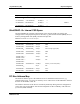
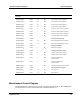
Bit AccessDefaultDescriptionName
6 ETH3 EN Status of Ethernet interface 3
0: Disableda
1: Enableda
0
2
r
7 Reserved Always zero 0
2
r
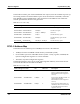
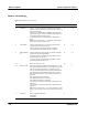
User LED Control Registers
The following registers control front panel LED related features.a
LED Control Register 1
This register is used to switch between the different operation modes of LED 1.
Address: 1FF.F160.0110
16
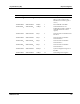
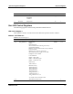
Table 27: LED Control Register 1
Bit
Name Description Default Access
4..0 LED_DISPLAY Board status
00000
2
a:
Red: Board reset
Weak red: Board abort (during reset access)
Green: Board running
Blinking red/weak red: No PCI activity within the
last two seconds
Blinking green: No boot code found
Weak red: 12V power supply on the VME
backplane is not available
00000
2
r/w
aa aa User LED mode
00100
2
a: LED is OFF
00001
2
a: LED shines green
00010
2
a : LED shines red
aa
aa aa IDE activity
10011
2
: IDE 1/2a
aa
aa aa Ethernet activity
11000
2
: Ethernet 1a
11001
2
: Ethernet 2a
11010
2
: Ethernet 3a
11011
2
: Ethernet 4a
11100
2
: Ethernet 1/3a
11101
2
: Ethernet 2/4
11111
2
: Ethernet 1/2/3/4
aa
aa aa At all other values, the LED is OFF. aa
7..5
aa These bits are always zero r