
User's Manual


Maps and Registers System Configuration Registers
116 SPARC/CPU−56T
Address: 1FF.F160.0100
16
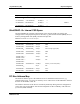
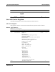
Table 26: Miscellaneous Control Register
Bit
Name Description Default Access
0 TSOP EN Used to switch between PLCC PROM access and flash
memory access in the address space for CS0#. After reset,
this bit is cleared (0).a
0: If SW1−2 is OFF, the PLCC PROM is available in the
CS0# address space. If SW1−2 is ON the flash memory is
available in the CS0# address space.
1: The flash memory is available in the CS0# address
space.
Note: You can only write a "1" to this bit. After doing so,
it can not be cleared anymore to "0".a
0
2
r/w
1 PS/2 BACK Used to switch between a rear connected and a front
connected PS/2 keyboard/mouse.a
0: Front panel PS/2 keyboard/mouse is enabled.
1: Rear panel PS/2 keyboard/mouse is enabled.
0
2
r/w
2 SER2_RS422E
N
Used to enable the voltage supply for the RS−422 cable
connected to the serial B interface.a
0: Voltage supply is disabled. The ring indicator of the
serial B interface can be used.a
1: Voltage supply is enabled. The ring indicator of the
serial interface B cannot be used.a
0
2
r/w
3..4 − These bits are always zero. 0
2
r
5..7 ETH1/3CTRL These bits determine whether Ethernet interface 1 at the
front panel or Ethernet interface 3 via IOBP is active. The
selection is made by OpenBoot or VxWorks at board
start−up. Per default, the selection is done automatically
and depends on which Ethernet interface has a link. If
both or no interfaces have a link, Ethernet interface 1 is
preferred
000
2
: No change of current status
0x1
2
: Ethernet interface 1 is enabled
010
2
: Ethernet interface 3 is enabled
1x1
2
: Selection is made automatically with preference of
interface 1
110
2
: Selection is made automatically with preference of
interface 3
Note: You can only write a "1" to each of these bits. After
doing so, the respective bit can not be cleared anymore to
"0".a
−w
5
ETH1 EN Status of Ethernet interface 1
0: Disabled
1: Enableda
1
2
r