
User's Manual


Physical Memory Map Maps and Registers
SPARC/CPU−56T 111
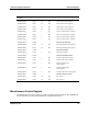
Physical Address Range PA<41..0> DIMM TypeMemory LocationBankSize
001.0000.0000
16
aa − 001.0FFF.FFFF
16
256 MByte 4 SPARC/MEM−550 DIMM 2
001.1000.0000
16
aa − 001.1FFF.FFFF
16
256 MByte 5 aa aa
001.8000.0000
16
a− 001.8FFF.FFFF
16
256 MByte 6 aa DIMM 3
001.9000.0000
16
a− 001.9FFF.FFFF
16
256 MByte 7 aa aa
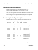
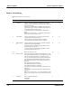
UltraSPARC−IIi+ Internal CSR Space
The UltraSPARC−IIi+ internal configuration space registers (CSR) are used for the
configuration of the peripheral parts of the CPU, e.g. the PCI bus module (PBM), the I/O
memory management unit (IOM), and the interrupt unit.
Table 22: UltraSPARC−IIi+ Internal CSR Space
Physical Address Range Size Description
1FE.0000.0000
16
a − 1FE.0000.01FF
16
512 Byte PBM
1FE.0000.0200
16
a − 1FE.0000.03FF
16
512 Byte IOM
1FE.0000.0400
16
a − 1FE.0000.1FFF
16
7 KByte PCI interrupt engine (PIE)
1FE.0000.2000
16
a − 1FE.0000.5FFF
16
16 KByte PBM
1FE.0000.6000
16
a − 1FE.0000.9FFF
16
12 KByte PIE
1FE.0000.A000
16
a −
1FE.0000.A7FF
16
2 KByte IOM
1FE.0000.A800
16
a −
1FE.0000.EFFF
16
22 KByte PIE
1FE.0000.F000
16
a − 1FE.00FF.F018
16
23 MByte Memory control unit (MCU)
1FE.00FF.F020
16
aa 8 Byte PIE
1FE.00FF.F028
16
a − 1FE.00FF.FFFF
16
4 KByte MCU
1FE.0100.0000
16
a − 1FE.0100.0041
16
65 Bytea PBM
PCI Bus Address Map
The PCI bus address space is divided into areas for the different PCI accesses, e.g.
configuration access, I/O access or memory access. These areas are distributed to the PCI
devices on the SPARC/CPU−56.
a
The address allocation of the devices is made dynamically during the PCI configuration
cycles after reset in OpenBoot. The allocation depends on the availibility of PCI devices
(I/O board, PMC module).