
User's Manual


System Configuration Registers Maps and Registers
SPARC/CPU−56T 121
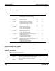
Bit AccessDefaultDescriptionName
5..3 0 Reserved 000
2
r
6 STAT ACFAIL This bit reflects the state of the VMEbus low active
ACFAIL signal, i.e. whether a failure of the power
supply occurred.
0: The ACFAIL# signal is inactive (high).
1: The ACFAIL# signal is active (low).
0
2
r
7
STAT SYSFAIL This bit reflects the state of the VMEbus low active
SYSFAIL signal, i.e. whether a failure of the power
supply occurred.
0: The SYSFAIL# signal is inactive (high).
1: The SYSFAIL# signal is active (low).
0
2
r
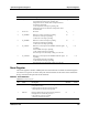
Watchdog Timer Registers
The watchdog timer is used to reset the board after a defined time interval, if no software
trigger occurred. Before the watchdog timer runs out, an interrupt will be generated if it is
enabled in the Interrupt Enable Control register. To enable the watchdog, switch SW1−3
must be set to ON. For details, refer to
asection "Switch Settings" on pagea46.
The watchdog starts with the first trigger of the watchdog trigger bit in the Watchdog
Trigger register. After the watchdog is enabled, it is not possible to stop the watchdog.
The watchdog timer can be configured to reset the board after a certain time interval
which can vary between 125 ms and 1 hour. After reset, the time is set to 2.5 s for the reset
and to 1.25 s for the interrupt, which is compatible to the SPARC/CPU−54.
Watchdog Timer Control Register
The Watchdog Timer Control register is used to set the time−out for the watchdog timer.
Note:aIf the watchdog is running, you can only change the watchdog time to a smaller
value.