
User's Manual


Maps and Registers System Configuration Registers
120 SPARC/CPU−56T
Address: 1FF.F160.0113
16
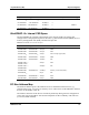
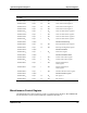
Table 30: LED Control Register 4
Bit
Name Description Default Access
4..0 LED_DISPLAY User LED mode
00000
2
: OFF
00001
2
a : Green
00010
2
a : Red
00011
2
a : Weak red
00101
2
a : Slow blinking green (1/2 Hz)
00110
2
a : Slow blinking red
00111
2
a : Slow blinking weak red
01001
2
a : Blinking green (1 Hz)
01010
2
a : Blinking red
01011
2
a : Blinking weak red
01101
2
a : Fast blinking green (2 Hz)
01110
2
a : Fast blinking reda
01111
2
a : Fast blinking weak reda
00000
2
r/w
aa aa Ethernet activity
11000
2
: Ethernet 1
11001
2
: Ethernet 2
11010
2
: Ethernet 3
11011
2
: Ethernet 4
11100
2
: Ethernet 1/3
11101
2
: Ethernet 2/4
11111
2
: Ethernet 1/2/3/4
aa
aa aa At all other values, the LED is OFF. aa
7..5
aa These bits are always zero. r
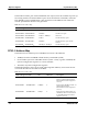
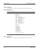
External Failure Status Register
The External Failure Status register is used to receive information of external failure
conditions: Overheating or power supply problems. All failure conditions can also be
configured as an interrupt (refer to Interrupt Registers" section).
Address: 1FF.F160.0120
16
Table 31: External Failure Register
Bit
Name Description Default Access
1..0 0 Reserved 00
2
r
2 TEMP_STAT This bit reflects the state of the temperature sensor
output.
0 : The temperature sensor did not detect a
temperature outside of the specified range.
1: The temperature sensor has detected a temperature
outside of the specified range.
0
2
r