
User's Manual


Maps and Registers Physical Memory Map
112 SPARC/CPU−56T
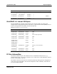
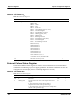
The PCI device PCIO, part of the UltraSPARC−IIi+ chip set, must be available at power up
for booting and has a fixed PCI address space. It has an interface to the EBus, where the
boot PROM is located. Additionally, it has an interface to the MII bus from where the
twisted−pair Ethernet interfaces are generated.
a
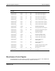
Table 23: PCI Bus Address Map
Address Range in PA<40:0>
Size Description
1FE.0100.0100
16
− 1FE.01FF.FFFF
16
24 MByte − 256 Byte PCI bus configuration space
1FE.0200.0000
16
− 1FE.02FF.FFFF
16
24 MByte PCI bus I/O space
1FE.0300.0000
16
− 1FE.FFFF.FFFF
16
4 GByte − 48 MByte Reserved
1FF.0000.0000
16
− 1FF.FFFF.FFFF
16
4 GBytea PCI bus memory space
1FF.F000.0000
16
− 1FF.F17F.FFFF
16
24 MByte PCI bus memory space for the
PCIO−2
1FF.F180.0000
16
− 1FF.FFFF.FFFF
16
256 MByte − 24 MByte PCI bus memory space
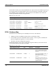
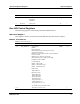
PCIO−2 Address Map
The PCIO−2 has an address space of 24 MByte in total. It is divided into:
S 16 MByte for the boot PROM or flash memory on the EBus (CS0#)
S Seven address spaces for other EBus devices (CS1# − CS7#), e.g. RTC/NVRAM, the
System Configuration registers or a serial controller.
S The PCIO−2 System Configuration registers
The detailed memory map is given in the following table. Memory areas which are not
covered in the table are reserved for the EBus.
a
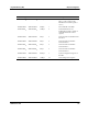
Table 24: PCIO−2 Address Map
Address Range in PA<40:0>
Size EBus CS# Description
1FF.F000.0000
16
a − 1FF.F00F.FFFF
16
1 MByte 0 PLCC PROM on the EBus (if
SW1−1 is OFF and if bit 0 of the
Miscellaneous Control register is
set to 0)
1FF.F010.0000
16
a − 1FF.F0FF.FFFF
16
15 MByte 0 Reserved for the EBus (if SW1−1 is
OFF and if bit 0 of the
Miscellaneous Control register is
set to 0)
1FF.F000.0000
16
a − 1FF.F00F.FFFF
16
1 MByte 0 Boot section of flash memory on
the EBus (if SW1−1 is ON or if bit
0 of the Miscellaneous Control
register is set to 1)