DS-C33 II Series User’s Manual www.opti-ups.
Contents 1. Preface ........................................................................................................................................................... 3 1-1 Introduction ......................................................................................................................................... 3 1-2 Safe Instructions and Warnings ........................................................................................................... 3 2. System Framework.............
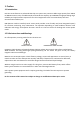
1. Preface 1-1 Introduction DS-C33 II series features an advanced DSP chip as a system core processor. Wide range capacity from 10KVA to 200KVA meets a verity of load demands and extends the capacity up to 400KVA through paralleling. High reliability and rapid transient response fit for critical equipments such as semiconductor, SMT and communication facilities, etc.
2. System Framework 2-1 Block Diagram (1) (2) (8) (3) (4) (5) (6) Fig.
2-2 System Major Module Function Introduction 2-2-1 Rectifier (1) (2) (3) (4) (5) (6) (7) (8) (9) (10) Utilization of SCRs inverts AC voltage to DC voltage. Combination of CPLD and DSP make the rectifier more stable and reliable. Over-voltage protection. DC voltage soft starter. Float charging and equalization charging modes support. Float charging time is adjustable and available on the display panel. Battery test can be done with continuous AC supply.
2-3 System Operation Modes 2-3-1 Normal Operation Fig. 2-3-1 Normal Operation AC mains power goes through the rectifier, the inverter, the STS to the load. 2-3-2 Bypass Operation Fig. 2-3-2 Bypass Operation AC mains power goes through the bypass path and the STS to the load. 2-3-3 Battery Supply Operation Fig. 2-3-3 Battery Supply Operation The power supplied from batteries goes through the inverter and the STS to the load.
2-3-4 Maintenance Bypass Operation Fig. 2-3-4 Maintenance Bypass Operation AC mains power goes through the maintenance bypass switch to the load. This mode is only for trained professionals to do regular system and cleaning maintenance. 2-3-5 EPO Switch Fig. 2-3-5 EPO Switch UPS is going to be turned off and outputs no power in this mode for emergency.
3. Touch Display Panel (HMI, Human Machine Interface) 3-1 Introduction Fig. 3-1 DS-C33 II has an 800x480px TFT touch screen display panel. It can be set and controlled, and its status and information are displayed on the display panel shown as Fig.3-1. 3-2 LCD Panel The display consists of main control, event log, user set, maintenance staff, advanced set, calibrate set and spec./service categories (tabs) and their corresponding pages.
3-2-2 Event log Up to 2400 events with time in total can be recorded on 6 pages shown as Fig.3-2-2-1. These are helpful for maintenance engineers to find root causes and solve issues fast. More functions: (1) PIP (Picture in picture) event log Different events are shown in separate windows as in Fig.3-2-2-2. (2) Logs can be exported to a portable disk. (3) Logs are erasable. Fig. 3-2-2-1 Fig.
3-2-3 User set User settings are available for end users to set/select language, battery test, charging mode, communication mode, password, dry contact programming, brand name/ hotline shown as Fig. 3-2-3-1. Password is required for access to this function and the default password is 000000. Successful access is shown as Fig. 3-2-3-2. Press Save Data and Enter buttons to avoid being reset by other people. Fig. 3-2-3-1 Fig.
3-2-4 Maintenance staff This function is only for professionals or qualified technicians. Professionals or qualified technicians will use the information to find the fault root causes and solve issues timely. Operations are shown as Fig. 3-2-4-1. Fig.
3-2-6 Calibrate set Calibration settings are available for professionals to set voltage, current and temperature, etc shown as Fig. 3-2-6-1. This function requires an advanced set password. Press Save Data and Enter buttons to avoid being reset by other people. Fig. 3-2-6-1 3-2-7 Spec./Service This function display specification details and service information shown as Fig. 3-2-7-1. Fig.
4. Fixation and Installation 4-1 Fixation 4-1-1 Transportation (1) Fig. 4-1-1a and Fig. 4-1-1b represent the packing. (2) UPS should be placed in the way indicated by the arrow on the carton. (3) In order to avoid danger during transportation, UPS or battery packs should be fastened tightly by ropes and placed in the center of truck front end as Fig. 4-1-1c illustrates. (4) Do not unpack the UPS during transportation.
U.P.S Fig. 4-1-1c Fig. 4-1-1d Fig.
4-1-2 Unpacking (1) (2) (3) (4) Cut off packing ropes and take out packing coverings as Fig. 4-1-2a, 4-1-2b and 4-1-2c illustrate. Unwrap PE coating. Unscrew screws of L fixers screwed on the pallet as Fig. 4-1-2d and 4-1-2e illustrate. Follow the arrow marks to unload the UPS as Fig. 4-1-2 illustrates. Fig. 4-1-2a Fig. 4-1-2b Fig. 4-1-2c Unscrew Fig. 4-1-2d Unscrew Fig. 4-1-2e Fig.
4-1-3 Placement and Environment (1) A UPS should be placed in a clean and air conditioned environment and with ambient temperature between 0℃ and +28℃. The operation temperature ranging from 10℃ to +25℃ is the best. (2) UPS can’t be closely placed against or surrounded by walls or other objects as it would prevent from good ventilation. An exhaust is in a rear of the UPS shown as Fig. 4-1-3a. (3) Make room for opening the door of the UPS cabinet.
4-1-4 Outline and Dimension 10 / 15 / 20 / 30K 120V / 208V & 220V / 380V Models
45 / 60K 120V / 208V Models 45 / 60 / 80 / 100 / 120K 220V / 380V Models
80 / 100 / 120K 120V / 208V Models
160 / 200K 220V / 380V Models
4-2 Installation 4-2-1 UPS Input / Output Specifications Frequency Topology Voltage Input 50 / 60Hz 3p3w and PE 220Vac, 380Vac 3p4w and PE 110 / 190Vac, 115 / 200Vac, 120 / 208Vac, 127 / 220Vac, 220 / 380Vac, 230 / 400Vac, 240 / 415Vac, 254 / 440Vac Output 50 / 60Hz 3p3w and PE 220Vac, 380Vac 3p4w and PE 110 / 190Vac, 115 / 200Vac, 120 / 208Vac, 127 / 220Vac, 220 / 380Vac, 230 / 400Vac, 240 / 415Vac, 254 / 440Vac Table 4-2-1 Input / Output NFB Specifications Capacity Voltage Max Input Input Current NFB 120
4-2-2 Cable Specifications 600V PVC Insulated Hard Copper Stranded Wire Safe Current Table (60℃ Insulation, Ambient Temperature under 30℃) Number of Number of Sectional Area Sectional Area Type Strands/ Safe Current Strands/ Safe Current (mm2) (mm2) Diameter Diameter 3.5 7 / 0.8 37 80 19 / 2.3 257 5.5 7 / 1.0 49 100 19 / 2.6 298 8 7 / 1.2 61 125 19 / 2.9 344 Hard 14 7 / 1.6 88 150 37 / 2.3 395 Copper 22 7 / 2.0 115 200 37 / 2.6 469 Strand 30 7 / 2.3 139 250 61 / 2.3 556 Wire 38 7 / 2.6 162 325 61 / 2.
4-2-4 Terminal Definitions (1) I/R : Rectifier Input R Phase (2) I/S : Rectifier Input S Phase (3) I/T : Rectifier Input T Phase (4) I/N : Input Neutral Line (5) I2/R : Slave UPS Input R Phase (from slave UPS input R phase for paralleling system) (6) I2/S : Slave UPS Input S Phase (from slave UPS input S phase for paralleling system) (7) I2/T : Slave UPS Input T Phase (from slave UPS input T phase for paralleling system) (8) BP/R : Bypass Input R Phase (9) BP/S : Bypass Input S Phase (10) BP/T : Bypass Inpu
4-2-6 Terminals 10 / 15 / 20 / 30K 120V / 208V & 220V / 380V Models Master / Slave UPS I/R I/N I2/R I/S I/T I2/S I2/T BP/R BP/S BP/T BP/N O/N O/R O/S O/T B+ G B- O/R O/S O/T 45 / 60K 120V / 208V Models 45 / 60 / 80 / 100/ 120K 220V / 380V Models Master UPS I/R I/N I2/R I/S I/T I2/S I2/T BP/R BP/S BP/T BP/N O/N B+ G B- O/R O/S O/T Slave UPS I/R I/N I2/N I/S I/T BP/N O/N BP/R BP/S BP/T B+ G B-
80 / 100 / 120K 120V / 208V Models Slave UPS I/R BP/R BP/S BP/T BP/N O/N B+ O/R G O/S BO/T I/S I/T I/N
5. Operation Procedures 5-1 Power-on 5-1-1 Initial Power-on Procedures (1) Switches BAT Switch: for switching on/off batteries. SPS Switch: for switching on/off the power board. S1 Switch: for switching on/off the second AC mains power or the bypass of the model with an input transformer. S2 Switch: for switching on/off the primary AC mains power. S3 Switch: for switching on/off the output S4 Switch: for switching on/off the manual bypass during maintenance.
5-1-2 Normal Power-on Procedures When the initial power-on procedure is done and the UPS is turned on. Press Inverter ON button on the HMI control panel and Yes button on the pop-up window to restart the UPS. It will be turned on after 3 minutes.
5-2 Power-off 5-2-1 Normal Power-off Procedures Press Inverter OFF button on the HMI control panel and Yes button on the pop-up window to shut down the UPS. UPS operation mode changes from inverter to bypass, and a dialogue window pops up for this status. 5-2-2 Complete Power-off Procedures Follow Fig. 5-1-1. 5-3 Maintenance Bypass 5-3-1 Maintenance Bypass Procedures Follow Fig. 5-3. 5-3-2 DS10KC33 / 15KC33 II Inbuilt Battery Replacement Procedures (1) Transferring to bypass mode Follow Fig.
Fig. 5-3 Maintenance Bypass Workflow *) for 10K~30KVA models, fuses must be installed before the initial power-on operation.
5-6 Dry Contact Communication (1) PCB-3308 Dry contact layout shown as Fig. 5-7-1. (2) PCB-3308 Dry contact function definitions listed in Table 5-7-2. Fig.
6. Maintenance and Storage (1) (2) (3) (4) Clean the UPS placement chamber and the UPS itself from dust every 6 months. Recharge and discharge batteries every 3 months to maintain their lifetime. Pay attention to the temperature and humidity of the chamber. When storing a UPS, disconnect all cables (take out the fuses or batteries for battery-inbuilt models) and wrap the UPS with PE coating.
8. Specifications Model Capacity Rated Power DS10K C33 II 10KVA 8KW DS15K DS20K DS30K DS45K C33 II C33 II C33 II C33 II 15KVA 20KVA 30KVA 45KVA DS60K DS80K DS100K C33 II C33 II C33 II 60KVA 80KVA 100KVA 12KW 48KW 16KW 24KW 36KW Power Factor 64KW 80KW DS120K C33 II 120KVA 96KW DS160K C33 II 160KVA DS200K C33 II 200KVA 128KW 160KW 0.
Model Battery Configuration DS10K DS15K DS20K DS30K DS45K DS60K DS80K C33 II C33 II C33 II C33 II C33 II C33 II C33 II DC192V (12V × 16pcs) DC360V (12V × 30pcs) Backup Time DS100K DS120K C33 II C33 II DC360V (12V × 30pcs) DS160K DS200K C33 II C33 II DC384V (12V × 32pcs) Depends on overall battery capacity Noise <60dB Operating Temperature 0~40℃ Storage Temperature -25℃~55℃ Storage Altitude <10000M Operating Altitude <3500M Relative Humidity 90% Non Condensing Physical Dimensions Width 530
9. Contact Information OPTI-UPS USA: Tel: +1-909-869-5700 Fax: +1-909-869-5730 info@opti-ups.com www.opti-ups.com OPTI-UPS Europe: Tel: +31-40-401-50-00 Tel: +31-40-262-80-57 Fax: +31-40-254-60-06 eu@opti-ups.com www.opti-ups.com OPTI-UPS Middle East: Tel: +9714-8819-838 Fax: +9714-8819-938 mea@opti-ups.com www.opti-ups.com OPTI-UPS Australia & New Zealand: Tel: +64-9-441-6470 Fax: +64-9-441-6490 aunz@opti-ups.com www.opti-ups.