
Data Sheet


PCA9685 All information provided in this document is subject to legal disclaimers. © NXP Semiconductors N.V. 2015. All rights reserved.
Product data sheet Rev. 4 — 16 April 2015 17 of 52
NXP Semiconductors
PCA9685
16-channel, 12-bit PWM Fm+ I
2
C-bus LED controller
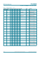
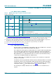
Example 1: (assumes that the LED0 output is used and
(delay time) + (PWM duty cycle) 100 %)
Delay time = 10 %; PWM duty cycle = 20 % (LED on time = 20 %; LED off time = 80 %).
Delay time = 10 % = 409.6 ~ 410 counts = 19Ah.
Since the counter starts at 0 and ends at 4095, we will subtract 1, so delay time = 199h
counts.
LED0_ON_H = 1h; LED0_ON_L = 99h (LED start turn on after this delay count to
409)
LED on time = 20 % = 819.2 ~ 819 counts.
LED off time = 4CCh (decimal 410 + 819 1 = 1228)
LED0_OFF_H = 4h; LED0_OFF_L = CCh (LED start turn off after this count to 1228)
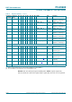
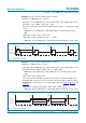
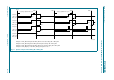
Example 2: (assumes that the LED4 output is used and
(delay time) + (PWM duty cycle > 100 %)
Delay time = 90 %; PWM duty cycle = 90 % (LED on time = 90 %; LED off time = 10 %).
Delay time = 90 % = 3686.4 ~ 3686 counts 1 = 3685 = E65h.
LED4_ON_H = Eh; LED4_ON_L = 65h (LED start turn on after this delay count to
3685)
LED on time = 90 % = 3686 counts.
Since the delay time and LED on period of the duty cycle is greater than 4096 counts,
the LEDn_OFF count will occur in the next frame. Therefore, 4096 is subtracted from
the LEDn_OFF count to get the correct LEDn_OFF count. See Figure 9
, Figure 10 and
Figure 11
.
LED off time = CCBh (decimal 3685 + 3686 = 7372 4096 = 3275)
LED4_OFF_H = Ch; LED4_OFF_L = CBh (LED start turn off after this count to 3275)
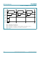
Fig 7. LED output, example 1
0
STOP
example 1
LEDn_ON
LEDn_OFF
4095 0
409
819
(LED ON)
LED OFF
1228
4095
0 4095 0
002aad812
409
1228
409
1228
409
1228
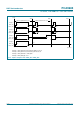
Fig 8. LED output, example 2
0
STOP
example 2
LEDn_ON
LEDn_OFF
4095
0
3685
4095 0 4095 0
002aad813
3275
3685
3275
3685
LED ON (90 %)