
Data Sheet


TPS731
www.ti.com
SBVS034N –SEPTEMBER 2003–REVISED DECEMBER 2015
Feature Description (continued)
The TPS731xx uses an internal charge pump to develop an internal supply voltage sufficient to drive the gate of
the NMOS pass element above V
OUT
. The charge pump generates approximately 250 μV of switching noise at
approximately 4 MHz; however, charge-pump noise contribution is negligible at the output of the regulator for
most values of I
OUT
and C
OUT
.
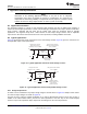
7.3.2 Internal Current Limit
The TPS731xx internal current limit helps protect the regulator during fault conditions. Foldback current limit
helps to protect the regulator from damage during output short-circuit conditions by reducing current limit when
V
OUT
drops below 0.5 V. See Figure 10.
Note from Figure 10 that approximately –0.2 V of V
OUT
results in a current limit of 0 mA. Therefore, if OUT is
forced below –0.2 V before EN goes high, the device may not start up. In applications that work with both a
positive and negative voltage supply, the TPS731xx should be enabled first.
7.3.3 Enable Pin and Shutdown
The enable pin (EN) is active high and is compatible with standard TTL-CMOS levels. A V
EN
below 0.5 V
(maximum) turns the regulator off and drops the GND pin current to approximately 10 nA. When EN is used to
shutdown the regulator, all charge is removed from the pass transistor gate, and the output ramps back up to a
regulated V
OUT
(see Figure 21).
When shutdown capability is not required, EN can be connected to V
IN
. However, the pass gate may not be
discharged using this configuration, and the pass transistor may be left on (enhanced) for a significant time after
V
IN
has been removed. This scenario can result in reverse current flow (if the IN pin is low impedance) and faster
ramp times upon power up. In addition, for V
IN
ramp times slower than a few milliseconds, the output may
overshoot upon power up.
The current limit foldback can prevent device start-up under some conditions. See Internal Current Limit.
7.3.4 Reverse Current
The NMOS pass element of the TPS731xx provides inherent protection against current flow from the output of
the regulator to the input when the gate of the pass device is pulled low. To ensure that all charge is removed
from the gate of the pass element, the EN pin must be driven low before the input voltage is removed. If this is
not done, the pass element may be left on due to stored charge on the gate.
After the EN pin is driven low, no bias voltage is needed on any pin for reverse current blocking. The reverse
current is specified as the current flowing out of the IN pin due to voltage applied on the OUT pin. There will be
additional current flowing into the OUT pin due to the 80-kΩ internal resistor divider to ground (see Figure 29 and
Figure 30).
For the TPS73101, reverse current may flow when V
FB
is more than 1.0 V above V
IN
.
7.4 Device Functional Modes
7.4.1 Normal Operation With 1.7 V ≤ V
IN
≤ 5.5 V and V
EN
≥ 1.7 V
The TPS731xx family requires an input voltage of at least 1.7 V to function properly and attempt to maintain
regulation.
When operating the device near 5.5 V, take care to suppress any transient spikes that may exceed the 6.0-V
absolute maximum voltage rating. The device should never operate at a DC voltage greater than 5.5 V.
Copyright © 2003–2015, Texas Instruments Incorporated Submit Documentation Feedback 13
Product Folder Links: TPS731