
Data Sheet


SCL
A4
A5
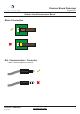
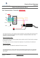
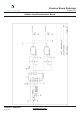
Ext. Communication Connector IMPORTANT
The 3.5mm connector on the Chestnut board is intended for communicating with external sensors,
using either 2 raw analogue signals or an I2C connection. The desired function of the 3.5mm
connector is selected in software.
Setup for Analogue Input:
Set the two ADC pins (A4 & A5) as analogue inputs, and then set the 3.5mm function to analogue
by setting Pin 10 “LOW”.
The analogue pins can also be configured as a digital pins, for push buttons, tilt switches etc.
Setup for I2C Input:
Set Pin 10 “HIGH”, then address the attached I2C device as normal.
It is important that only a 4-Pole 3.5mm Jack is used with the Chestnut board, as a 3 pole may
cause damage to the microcontroller. It should be noted that signal strength can degrade with
cable length.
August 2017
openbionics.com
Chestnut - Datasheet
GND
SDA
3.3V
10K
10K
10K
Pin 10
3.3V
GND
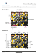
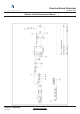
Electronic Switch
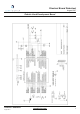
Robotic Hand Development Board
(SDA/A5)
(SCL/A4)
August 2017
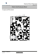
Chestnut Board Datasheet
5