
User Guide


CHAPTER 7: Routing, Channelizing and Muting Window
Studio 4 Manual 41
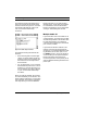
only one Studio 4, you’ll use only the first
eight rows and columns in the MIDI Rout-
ing, Channelizing and Muting areas. Also,
you'll use only eight of the timecode rout-
ing squares.
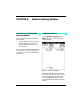
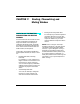
The RCM window illustrates its active
regions by dimming all unused portions
of the grid as shown in Figure 7.1. The
window's title bar indicates whether the
Studio 4 is connected to the Modem port,
Printer port, or both (2 cables).
RCM Window with Two Studio 4's
in a Single Network
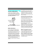
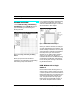
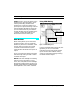
If you have a second Studio 4 connected
as shown in Figure 7.3, your Studio 4 net-
work contains sixteen MIDI ins and
sixteen MIDI outs. Rows 9-16 and col-
umns 9-16 represent the second Studio 4.
Figure 7.3: Two Networked Studio 4’s
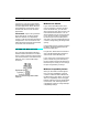
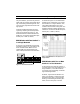
As shown in Figure 7.4, the entire RCM
window grid is active when you connect
two Studio 4's to a single network. Also,
notice that both Studio 4's are repre-
sented in the timecode routing area. The
window's title bar indicates whether the
network is connected to the Modem port,
Printer port, or both (2 cables).
Figure 7.4: RCM Window for Two Studio 4's in a
Single Network
RCM Window with Two or More
Studio 4's in Two Networks
As discussed in the previous sections, if
you have either one or two Studio 4’s in a
single network (or a 2-cable network),
you’ll have only one Routing, Channeliz-
ing and Muting window.
However, if you have two Studio 4 net-
works (one network connected to each
Macintosh serial port), you’ll have two
Routing, Channelizing and Muting win-
dows (one for each port). From the
OUT
MIDI OUT MIDI IN
SMPTE
IN
PORT B PORT A
B
THRU
A
THRU
9VDC 8
16
7
15
6
14
5
13
4
12
3
11
2
10
1
9
6
14
5
13
4
12
3
11
2
10
1
9
OUT
MIDI OUT MIDI IN
SMPTE
IN
PORT B PORT A
B
THRU
A
THRU
9VDC 8
16
7
15
6
14
5
13
4
12
3
11
2
10
1
9
6
14
5
13
4
12
3
11
2
10
1
9
MACINTOSH
Set to 9-16
Set to 1-8
Optional 2nd cable