
User's Manual

7
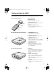
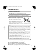
Getting to Know the UWL-1
The page numbers in parentheses show where you can find the main explanation for each item.
1
2
4
3
A Protective cap (9)
B USB connector (9)
Plugs into a USB port on your PC.
C Transmit indicator (9)
Lights up when the Transmitter is transmit-
ting.
D CH SELECT button (11, 14)
Used to set the Receiver’s ID and to select
the wireless channels.
■ Transmitter (UTX-1)
1
3
4
2
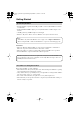
A STANDBY/ON button (13)
Sets the Receiver to On or Standby.
B CH SELECT button (11)
Used to set the Receiver’s ID and the Auto
Channel Select function.
C STANDBY indicator (11, 13)
Lights up when the Receiver is on Standby
and goes off when it’s On. Also used when
setting the Receiver’s ID.
D SYNC indicator (13)
Lights up when the Receiver is synchro-
nized with the Transmitter. Flashes when
it’s not synchronized.
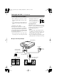
■ Receiver (RX-1) Front and Top
1
2
3
A LINE OUT
Use the included miniplug-to-RCA audio
cable to connect this jack to an analog audio
input on your audio system or powered
speakers.
B DIGITAL OUT (OPTICAL)
Use an optical audio cable to connect this
output to an optical audio input on your
audio system. (Digital recording is not pos-
sible via this output.)
C DC IN 5V
Connect the included AC adapter, or dedi-
cated DC power cable (European model
only), here.
■ Receiver (RX-1) Rear
UWL-1_En.book Page 7 Monday, September 11, 2006 11:13 AM