
User's Manual

10
Setting Up the UWL-1
—Continued
■
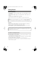
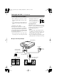
Typical Hookup Example
Connecting the Receiver (RX-1)
• Before making any connections, read the
manuals supplied with your other compo-
nents.
• Don’t connect the AC adapter until you’ve
completed and double-checked all connec-
tions.
Connection Color Coding
RCA-type audio connections are usually
color-coded: red and white. Use red plugs to
connect right-channel audio inputs and out-
puts (typically labeled “R”). Use white plugs
to connect left-channel audio inputs and out-
puts (typically labeled “L”).
•To prevent interference, keep audio cables
away from power cords and speaker cables.
• Push plugs in all the way to
make good connections
(loose connections can cause
noise or malfunctions).
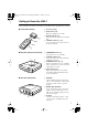
Optical Digital Jack
The UWL-1’s optical digital jack has a shut-
ter-type cover that opens when an optical plug
is inserted and closes when it’s removed.
Push the plug in all the way.
Caution:
• The optical cable is fitted with protective
caps. Before connecting it, remove the caps
and keep them in a safe place. When you
disconnect the cable, refit the caps.
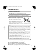
•To prevent shutter damage, hold the optical
plug straight when inserting and removing.
Right!
Wrong!
2
WAY POWERED SPEAKER SYSTEM
PHONES INPUT VOLUME
DIGITAL
AB
TREBLEBASS
OFF MAX
2
WAY POWERED SPEAKER SYSTEM
A
N
A
L
O
G
M
I
X
RL
Supplied miniplug-
to-RCA audio cable
AC adapter
Plug into
AC outlet
Optical digital cable
Powered
speakers
Audio component with
optical digital input
Audio input
Optical input
Receiver (RX-1)
UWL-1_En.book Page 10 Monday, September 11, 2006 11:13 AM