Contents Introduction ..................................... 2 AV Receiver TX-SR803/803E TX-SR703/703E TX-SR8370 Instruction Manual Connection .................................... 19 Turning On & First Time Setup..... 39 Basic Operation Playing your AV components ....... 48 Using the Tuner............................ 49 Enjoying the Listening Modes ..... 60 Thank you for purchasing an Onkyo AV Receiver. Please read this manual thoroughly before making connections and plugging in the unit.
WARNING: TO REDUCE THE RISK OF FIRE OR ELECTRIC SHOCK, DO NOT EXPOSE THIS APPARATUS TO RAIN OR MOISTURE. CAUTION: TO REDUCE THE RISK OF ELECTRIC SHOCK, DO NOT REMOVE COVER (OR BACK). NO USER-SERVICEABLE PARTS INSIDE. REFER SERVICING TO QUALIFIED SERVICE PERSONNEL.
Precautions 1. Recording Copyright—Unless it’s for personal use only, recording copyrighted material is illegal without the permission of the copyright holder. 2. AC Fuse—The AC fuse inside the unit is not userserviceable. If you cannot turn on the unit, contact your Onkyo dealer. 3. Care—Occasionally you should dust the unit all over with a soft cloth. For stubborn stains, use a soft cloth dampened with a weak solution of mild detergent and water. Dry the unit immediately afterwards with a clean cloth.
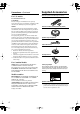
Precautions—Continued For U.S. models Supplied Accessories Make sure you have the following accessories: FCC Information for User CAUTION: The user changes or modifications not expressly approved by the party responsible for compliance could void the user’s authority to operate the equipment. NOTE: This equipment has been tested and found to comply with the limits for a Class B digital device, pursuant to Part 15 of the FCC Rules.
Contents Introduction Important Safety Instructions ....................2 Precautions .................................................3 Supplied Accessories.................................4 Features .......................................................6 Getting to Know the AV Receiver ..............7 Remote Controller.....................................13 Connection Connecting Your Speakers ......................19 Connecting Antenna .................................22 Connecting Your Components .....
Features TX-SR803/803E, TX-SR703/703E, and TX-SR8370 Amplifier • • • • • 7-channel amplifier Optimum Gain Volume Circuitry Zone 2 capability WRAT (Wide Range Amplifier Technology) Massive High Current Power Supply (H.C.P.S.
Getting to Know the AV Receiver Front Panel 1 23 4 5 6 7 MASTER VOLUME STANDBY/ON STANDBY ZONE 2 POWER ON OFF PURE AUDIO MULTI CH DVD VIDEO 1 VIDEO 2 VIDEO 3 VIDEO 4 PHONO TAPE TUNER CD DISPLAY PUSH TO OPEN 9 J Front flap 8 Not North American and Australian models Push here to open the flap The actual front panel has various logos printed on it. They are not shown here for clarity. For detailed information, see the pages in parentheses.
Getting to Know the AV Receiver—Continued K L M N O P QR S T STEREO DIMMER PHONES ZONE 2 OFF TONE MEMORY LISTENING MODE TUNING MODE U RETURN PRESET CLEAR ENTER X SETUP MIC PRESET DIGITAL TUNING On European Model S VIDEO VIDEO L AUDIO R Q PHONES OFF W VIDEO 4 INPUT SETUP ZONE 2 LEVEL ZONE 2 V TONE RT / PTY/ TP MEMORY STEREO LISTENING MODE RDS TUNING MODE CLEAR ZONE 2 LEVEL VIDEO 4 INPUT RETURN ENTER SETUP PRESET SETUP MIC PRESET TUNING DIGITAL S VIDEO VIDEO L
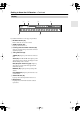
Getting to Know the AV Receiver—Continued Display 1 2 3 5 4 6 For detailed information, see the pages in parentheses. 1 MUTING indicator (58) Flashes while the AV receiver is muted. 2 ZONE 2 indicator (83) Lights up when Zone 2 is on. 3 Listening mode and format indicators (60) Show the selected listening mode and the format of digital input signals. 4 Tuning indicators (49) TUNED (49): Lights up when tuned to a radio station.
Getting to Know the AV Receiver—Continued Rear Panel TX-SR803/803E 12 3 4 N Not North American and Australian models O On some models 56 789 J K L M P QR S T U V W X Y TX-SR703/703E and TX-SR8370 12 3 5 6 P QR S T 10 7 8 9 KJ L U V N Not North American and Australian models O On some models M W X Y
Getting to Know the AV Receiver—Continued On North American Model Y Z A OPTICAL DIGITAL These optical digital audio inputs are for connecting components with optical digital audio outputs, such as CD players and DVD players. The optical digital audio output is for connecting a digital recorder with an optical digital input, such as a CD recorder. B COAXIAL DIGITAL These coaxial digital audio inputs are for connecting components with coaxial digital audio outputs, such as CD players and DVD players.
Getting to Know the AV Receiver—Continued N RS232 American and Australian models don’t have this port. This port is for connecting the AV receiver to home automation equipment and external controllers. O VOLTAGE SELECTOR (on some models) Some models have a voltage selector switch for compatibility with power systems around the world. Before you plug in such a model, make sure that the voltage selector is set to the correct voltage for your area.
Remote Controller Installing the Batteries 1 To open the battery compartment, press the small hollow and slide open the cover. Using the Remote Controller To use the remote controller, point it at the AV receiver’s remote control sensor, as shown below. Remote control sensor STANDBY indicator AV receiver 30˚ 2 3 Insert the three supplied batteries (AA/R6) in accordance with the polarity diagram inside the battery compartment. Slide the cover shut.
Remote Controller—Continued About the Remote Controller Modes Including the AV receiver, the remote controller can be used to control up to nine different components. The remote controller has a specific operating mode for use with each type of component. Modes are selected by using the eight REMOTE MODE buttons. ■ RECEIVER/TAPE Mode In RECEIVER/TAPE mode, you can control the AV receiver and an Onkyo cassette recorder connected via . RECEIVER/TAPE Mode RECEIVER/TAPE mode is used to control the AV receiver.
Remote Controller—Continued For detailed information, see the pages in parentheses. T MUTING button (58) Mutes or unmutes the AV receiver. A STANDBY button (39) Sets the AV receiver to Standby. B ON button (39) Turns on the AV receiver. C INPUT SELECTOR buttons (48) Used to select the input sources. D MULTI CH button (57) Selects the multichannel DVD input. E DIMMER button (58) Adjusts the display brightness. F Arrow [ ]/[ ]/[ ]/[ ] and ENTER buttons G H I J Used to select and adjust settings.
Remote Controller—Continued A STANDBY button DVD Mode Sets the DVD player to Standby. To set the remote controller to DVD mode, press the [DVD] REMOTE MODE button. B ON button Turns on the DVD player. C Number buttons Used to enter title, chapter, and track numbers, and to enter times for locating specific points. D TOP MENU button Selects a DVD’s top menu. E Arrow [ ]/[ ]/[ ]/[ ] and ENTER buttons A B ON STANDBY C Used to navigate menus and select items.
Remote Controller—Continued A STANDBY button CD, MD, and CDR Modes Sets the CD player or MD/CD recorder to Standby. To control an Onkyo CD player or a CD/MD recorder made by another manufacturer, press the [CD] REMOTE MODE button to select the CD remote controller mode. To control an Onkyo MD recorder or CD recorder, press the [MD] or [CDR] REMOTE MODE button to select the MD or CDR remote controller mode.
Remote Controller—Continued A STANDBY button HDD Mode Turns off the HDD-compatible component. HDD mode is for controlling Onkyo’s next generation HDD-compatible components. As of 2005, it can be used with the Onkyo DS-A1 Remote Interactive Dock and Apple iPod connected via . When Using the DS-A1: • Connect the DS-A1 to the TAPE IN or VIDEO 3 IN jacks. • Set the DS-A1’s RI MODE switch to HDD. • Set the AV receiver’s input display to HDD (see page 46). • Refer to the DS-A1’s instruction manual.
Connecting Your Speakers Enjoying Home Theater Thanks to the AV receiver’s superb capabilities, you can enjoy surround sound with a real sense of movement in your own home—just like being in a movie theater or concert hall. You can enjoy DVDs featuring DTS and Dolby Digital. With analog and digital TV, you can enjoy Dolby Pro Logic IIx and Onkyo’s own DSP surround listening modes. You can also enjoy THX Surround EX (THX-certified THX speaker system recommended).
Connecting Your Speakers—Continued Connecting a Powered Subwoofer Connecting Your Speakers Speaker Configuration For the best surround-sound experience, you should connect seven speakers and a powered subwoofer. The following table shows which channels you should use based on the number of speakers you have.
Connecting Your Speakers—Continued Speaker Connection Precautions Read the following before connecting your speakers: • You can connect speakers with an impedance of between 4 and 16 ohms. If the impedance of any of the connected speakers is 4 ohms or more but less than 6, be sure to set the minimum speaker impedance to 4 ohms (see page 46). If you use speakers with a lower impedance, and use the amplifier at high volume levels for a long period of time, the built-in amp protection circuit may be activated.
Connecting Antenna This section explains how to connect the supplied indoor FM antenna and AM loop antenna, and how to connect commercially available outdoor FM and AM antennas. The AV receiver won’t pick up any radio signals without any antenna connected, so you must connect the antenna to use the tuner. AM antenna push terminals FM antenna jack Connecting the Indoor FM Antenna The supplied indoor FM antenna is for indoor use only. 1 Attach the FM antenna, as shown.
Connecting Antenna—Continued Connecting an Outdoor FM Antenna Connecting an Outdoor AM Antenna If you cannot achieve good reception with the supplied indoor FM antenna, try a commercially available outdoor FM antenna instead. If good reception cannot be achieved using the supplied AM loop antenna, an outdoor AM antenna can be used in addition to the loop antenna, as shown.
Connecting Your Components AV Connection Color Coding About AV Connections RCA-type AV connections are usually color coded: red, white, and yellow. Use red plugs to connect right-channel audio inputs and outputs (typically labeled “R”). Use white plugs to connect left-channel audio inputs and outputs (typically labeled “L”). And use yellow plugs to connect composite video inputs and outputs. • Before making any AV connections, read the manuals supplied with your other AV components.
Connecting Your Components—Continued Connecting Audio and Video Signals to the AV Receiver By connecting both the audio and video outputs of your DVD player and other AV components to the AV receiver, you can switch the audio and video signals simultaneously simply by changing the input source on the AV receiver. : Signal Flow Video Video Audio Audio TV, projector, etc. DVD player, etc.
Connecting Your Components—Continued Connecting a TV or Projector Step 1: Video Connection Choose a video connection that matches your TV ( A , B , or C ), and then make the connection. Step 2: Audio Connection Choose an audio connection that matches your TV ( a , b , or c ), and then make the connection. • With connection a , you can listen to and record audio from your TV and listen in Zone 2. • To enjoy Dolby Digital and DTS, use connection b or c . (For recording, use a and b , or a and c .
Connecting Your Components—Continued Connecting a DVD player Step 1: Video Connection Choose a video connection that matches your DVD player ( A , B , or C ), and then make the connection. If you use connection A , you must connect the AV receiver to your TV with the same type of connection. Step 2: Audio Connection Choose an audio connection that matches your DVD player ( a , b , or c ), and then make the connection. • With connection a , you can listen to and record audio from a DVD and listen in Zone 2.
Connecting Your Components—Continued Hooking Up the Multichannel DVD Input If your DVD player supports multichannel audio formats such as DVD-Audio or SACD, and it has a multichannel analog audio output, you can connect it to the AV receiver’s multichannel DVD input. Use a multichannel analog audio cable, or several normal audio cables, to connect the AV receiver’s DVD IN FRONT L/R, CENTER, SURROUND L/R, SURR BACK L/R, and SUBWOOFER jacks to the 7.1-channel analog audio output on your DVD player.
Connecting Your Components—Continued Connecting a VCR or DVD Recorder for Playback In addition to video playback, with this hookup, you can use your VCR’s tuner to listen to your favorite TV programs via the AV receiver, useful if your TV has no audio outputs. If you have two video recorders (e.g., a VCR and a DVD recorder), connect one recorder to the VIDEO 1 IN jacks, as shown here, and connect the other recorder to the VIDEO 2 IN jacks in the same way.
Connecting Your Components—Continued Connecting a VCR or DVD Recorder for Recording If you have two video recorders (e.g., a VCR and a DVD recorder), connect one recorder to the VIDEO 1 OUT jacks, as shown here, and connect the other recorder to the VIDEO 2 OUT jacks in the same way. Step 1: Video Connection Choose a video connection that matches your VCR or DVD recorder ( A or B ), and then make the connection.
Connecting Your Components—Continued Connecting a Satellite, Cable, Set-top box, or Other Video Source Step 1: Video Connection Choose a video connection that matches the video source ( A , B , or C ), and then make the connection. If you use connection A , you must connect the AV receiver to your TV with the same type of connection. Step 2: Audio Connection Choose an audio connection that matches the video source ( a , b , or c ), and then make the connection.
Connecting Your Components—Continued Connecting a Camcorder, Games Console, or Other Device Step 1: Video Connection Choose a video connection that matches the camcorder or console ( A or B ), and then make the connection. Step 2: Audio Connection Choose an audio connection that matches the camcorder or console ( a or b ), and then make the connection.
Connecting Your Components—Continued Connecting a CD Player Step 1: Choose a connection that matches your CD player ( a , b , or c ), and then make the connection. b c COAXIAL IN 2 OPTICAL IN 3 a IN L R CD Connect one or the other L COAXIAL OUT OPTICAL OUT R AUDIO OUT CD player • With connection a , you can listen to and record audio from the CD player and listen in Zone 2. • To connect the CD player digitally, use connection b or c . (For recording, use a and b , or a and c .
Connecting Your Components—Continued Connecting a Cassette, CDR, MiniDisc, or DAT Recorder Step 1: Choose a connection that matches the recorder ( a , b , c , or d ), and then make the connection. b a IN COAXIAL IN 2 L R c TAPE OPTICAL a IN 4 L d OPTICAL R TAPE Connect one or the other L COAXIAL OUT OPTICAL OUT OPTICAL IN R AUDIO IN L R AUDIO OUT Cassette, CDR, MD, etc. • With connection a , you can play and record and listen in Zone 2.
Connecting Your Components—Continued Connecting Onkyo Components Step 1: Make sure that each Onkyo component is connected to the AV receiver with an analog audio cable (RCA). Step 2: Make the With connection. (Remote Interactive), you can use the following special functions: Auto Power On/Standby When you start playback on a component connected via , if the AV receiver is on Standby, it will automatically turn on and select that component as the input source.
Connecting Your Components—Continued Connecting Components with HDMI (TX-SR803/803E Only) About HDMI Designed to meet the demands of digital TV, HDMI (High Definition Multimedia Interface) is a new digital interface standard for connecting TVs, projectors, DVD players, set-top boxes, and other video components. Until now, several separate video and audio cables have been required to connect AV components.
Connecting Your Components—Continued Making HDMI Connections Step 1: Use HDMI cables to connect the TX-SR803/803E’s HDMI jacks to your HDMI-compatible DVD player, TV, projector, and so on. Step 2: Assign each HDMI IN to an input selector in the HDMI Video setup (see page 43). Video Signal Flow Chart Digital video signals received at HDMI IN 1 and 2 are only output by the HDMI OUT and sent to your TV. Composite video, S-Video, and component video input signals are not output by the HDMI OUT.
Connecting Your Components—Continued Connecting the Power Cords of Other Components The AV receiver has AC outlets on its rear panel that can be used to connect the power cords of other components that you intend to use with the AV receiver. These components can then be left turned on so that they turn on and off as and when the AV receiver is turned on and set to Standby. AC OUTLETS AC 120 V 60 Hz SWITCHED TOTAL 120W 1A MAX. AC OUTLETS AC 230-240 V 50 Hz SWITCHED TOTAL 100 W MAX.
Turning On the AV Receiver • North American and Australian models • Other models STANDBY/ON STANDBY indicator STANDBY/ON STANDBY indicator STANDBY/ON STANDBY STANDBY ZONE 2 ZONE 2 POWER ON PURE AUDIO MULTI CH DVD OFF PURE AUDIO VIDEO 1 MULTI CH DVD STANDBY V1 V2 TV INPUT I STANDBY/ON STANDBY ON ON V3 1 2 3 + V4 MULTI CH DVD T V CH 4 5 6 - CD TAPE TUNER 7 8 9 0 CLEAR T V VOL PHONO VIDEO 1 +10 11 --/ --- 10 INPUT SELECTOR 12 MACRO 1 2 3 ZONE2 REMOTE MO
First Time Setup This section explains the settings that you need to make before using the AV receiver for the very first time. 2 Put the speaker setup microphone in the listening position.
First Time Setup—Continued 3 ENTER Press [ENTER]. The automatic speaker setup starts. The test tone is output by each speaker in turn. The microphone picks up the sound and feeds it back to the AV receiver, where it’s used to calculate the optimum speaker settings. The whole process takes about 2 minutes. 5 Disconnect the speaker setup microphone. Auto Speaker Setup ======================= Please,unplug Setup Mic. Auto Speaker Setup ======================== Do not unplug Setup Mic. Please, keep quiet.
First Time Setup—Continued ■ Checking the Results If you selected “Check the Results” in step 4 on the previous page, the following menu appears and you can check the results of the automatic speaker setup. Auto Speaker Setup ======================== 1.Warning 2.Speaker Config 3.Speaker Distance 4.Speaker Level Adjust 5.Equalizer Settings When you’ve finished checking, press the [RETURN] button to return to the menu in step 4.
First Time Setup—Continued 1 HDMI Video Setup (TX-SR803/803E Only) ON STANDBY V1 2 TV INPUT I V2 RECEIVER V3 1 2 3 + V4 MULTI CH DVD T V CH 4 5 6 - CD TAPE TUNER 7 8 9 0 CLEAR ENTER T V VOL PHONO +10 11 --/--- 10 INPUT SELECTOR 12 MACRO 1 1 2 3 ZONE2 ENTER REMOTE MODE RECEIVER DVD CD HDD VCR CABLE SAT CDR MD TAPE/AMP TV Use the Up and Down [ ]/[ ] buttons to select “0.HDMI Video,” and then press [ENTER]. The HDMI Video menu appears. 0.
First Time Setup—Continued Component Video Setup ON STANDBY V1 V2 1 RECEIVER TV INPUT I 2 V3 1 2 3 + V4 MULTI CH DVD T V CH - 4 5 6 CD TAPE TUNER 7 8 9 0 CLEAR ENTER T V VOL PHONO +10 11 --/--- 10 INPUT SELECTOR 1 2 3 ZONE2 REMOTE MODE RECEIVER DVD CD HDD VCR CABLE SAT CDR MD TAPE/AMP ENTER TV SLEEP DIMMER 2 P TO MEN U Use the Up and Down [ ]/[ ] buttons to select “1. Component Video,” and then press [ENTER]. The Component Video menu appears.
First Time Setup—Continued Digital Audio Input Setup ON STANDBY V1 V2 V3 1 2 3 + V4 MULTI CH DVD T V CH - 1 RECEIVER TV INPUT I 4 5 6 CD TAPE TUNER 7 8 9 0 CLEAR 2 T V VOL PHONO +10 Press the [RECEIVER] button, followed by the [SETUP] button. The main menu appears onscreen. 11 --/--- 10 INPUT SELECTOR ENTER 12 Use the Up and Down [ ]/[ ] buttons to select “2. Digital Input,” and then press [ENTER]. The Digital Input menu appears.
First Time Setup—Continued Changing the Input Display Minimum Speaker Impedance If you connect an -capable Onkyo MiniDisc recorder, CD recorder, or next generation HDD-compatible component to the TAPE IN/OUT or VIDEO 3 IN jacks, for to work properly, you must change this setting. This setting can only be changed on the AV receiver. MASTER VOLUME STANDBY/ON STANDBY ZONE 2 POWER ON If the impedance of any speaker is 4 ohms or more but less than 6, set the Minimum Speaker Impedance to 4 ohms.
First Time Setup—Continued TV Format Setup (not North American models) You must specify the TV system used in your area. 1 RECEIVER 2 ENTER ENTER Press the [RECEIVER] button, followed by the [SETUP] button. The main menu appears onscreen. Use the Up and Down [ ]/[ ] buttons to select “8. Hardware Setup,” and then press [ENTER]. The Hardware Setup menu appears. AM Frequency Step Setup (on some models) You must specify the AM frequency step used in your area.
Playing Your AV Components Basic AV Receiver Operation ON STANDBY V1 V2 TV INPUT I 3 MASTER VOLUME STANDBY/ON 1 STANDBY ZONE 2 1 2 3 + V4 MULTI CH DVD T V CH - 4 5 6 CD TAPE TUNER 7 8 9 0 CLEAR T V VOL PHONO POWER ON V3 +10 OFF MULTI CH PURE AUDIO DVD VIDEO 1 VIDEO 2 VIDEO 3 VIDEO 4 PHONO TAPE TUNER CD 11 --/ --- 10 INPUT SELECTOR DISPLAY 12 MACRO 1 2 3 ZONE2 PUSH TO OPEN REMOTE MODE 1 RECEIVER DVD CD HDD VCR CABLE SAT CDR MD TAPE/AMP TV S
Listening to the Radio ■ Manual Tuning Mode Listening to AM/FM Stations 1 TUNING MODE TUNING Press the [TUNING MODE] button so that the AUTO indicator disappears from the display. TUNING MODE MASTER VOLUME STANDBY/ON STANDBY ZONE 2 2 POWER ON OFF MULTI CH PURE AUDIO DVD VIDEO 1 VIDEO 2 VIDEO 3 PHONES ZONE 2 OFF TONE DIMMER STEREO MEMORY LISTENING MODE ZONE 2 LEVEL PHONO VIDEO 4 TUNING MODE CLEAR TAPE TUNER CD DISPLAY Press and hold the TUNING Up or Down [ ]/[ ] button.
Listening to the Radio—Continued Using RDS (European Model Only) RDS only works with European models in areas where RDS broadcasts are available. When tuned to an RDS station, the RDS indicator appears. RDS indicator ■ What is RDS? RDS stands for Radio Data System and is a method of transmitting data in FM radio signals. It was developed by the European Broadcasting Union (EBU) and is available in most European countries. Many FM stations use it these days.
Listening to the Radio—Continued Displaying Radio Text (RT) 4 ENTER 5 ENTER To start the search, press [ENTER]. The AV receiver searches until it finds a station of the type you specified, at which point it stops briefly before continuing with the search.
Listening to the Radio—Continued Listening to XM Satellite Radio® (only for North American model) What’s XM Satellite Radio? There is a world beyond AM and FM. It is XM Satellite Radio. XM offers more than 150 digital channels of audio entertainment, including 100% commercial-free music channels, in the top markets in the U.S. Note: An XM Connect-and-Play™ antenna and monthly subscription are required to receive XM Satellite Radio. Visit www.xmradio.com for details.
Listening to the Radio—Continued ■ Category Search Mode Selecting XM Radio Channels There are two modes for selecting XM radio channels: Channel Search mode, which allows you to select any channel. Category Search mode, which allows you to select channels by category.
Listening to the Radio—Continued 11 - - / - - - 10 INPUT SELECTOR 12 MACRO TUNER DISPLAY 1 2 3 ZONE2 REMOTE MODE RECEIVER RECEIVER DVD CD HDD VCR CABLE SAT CDR MD TAPE/AMP TV SLEEP DIMMER MASTER VOLUME STANDBY/ON PM TO STANDBY ZONE 2 ENU MEN U + CH MULTI CH PURE AUDIO DVD VIDEO 1 VIDEO 2 VIDEO 3 PHONO VIDEO 4 TAPE TUNER CD DISC ALBUM DISPLAY ENTER VOL PHONES ZONE 2 OFF TONE DIMMER STEREO LISTENING MODE MEMORY TUNING MODE CLEAR VIDEO 4 INPUT SETUP RETURN
Listening to the Radio—Continued 4 ON STANDBY V1 V2 V3 1 2 3 + V4 MULTI CH DVD T V CH 4 5 6 - CD TAPE TUNER 7 8 9 0 CLEAR TV INPUT I 4-3.XM Antenna Aiming -------TUNER------------a.Signal Quality :100% [ | ] T V VOL PHONO +10 11 - - / - - - 10 INPUT SELECTOR Adjust the position of the XM antenna so that the “Signal Quality” is at least 70%.
Listening to the Radio—Continued Selecting Presets Presetting AM/FM Stations and XM Channels ON 1 STANDBY TV INPUT I 2, 4 3 V1 V2 MASTER VOLUME V3 STANDBY/ON 2 3 + MULTI CH DVD T V CH 1 STANDBY ZONE 2 POWER ON 4 OFF MASTER VOLUME MULTI CH PURE AUDIO DVD CD VIDEO 1 VIDEO 2 5 VIDEO 3 - 6 VIDEO 4 TAPE TAPE TUNER PHONO TUNER CD DISPLAY STANDBY/ON 7 STANDBY 8 9 ZONE 2 T V VOL POWER PHONES ZONE 2 ON OFF TONE DIMMER STEREO MEMORY +10 OFF LISTENING MODE ZONE
Using the Multichannel DVD Input Multichannel DVD Input Settings 1 ON STANDBY V1 V2 TV INPUT I MULTI CH RECEIVER V3 1 2 3 + V4 MULTI CH DVD T V CH 4 5 6 - CD TAPE TUNER 7 8 9 0 CLEAR T V VOL PHONO +10 11 --/--- 10 INPUT SELECTOR 12 2 MACRO 1 2 3 ZONE2 Use the Up and Down [ ]/[ ] buttons to select “4. Input Setup,” and then press [ENTER].
Common Functions This section explains functions that can be used with any input source. V1 V2 1 2 3 + V4 MULTI CH DVD T V CH 4 5 6 - CD TAPE TUNER 7 8 9 0 CLEAR You can adjust the volume of each speaker while listening to an input source. These temporary adjustments are cancelled when the AV receiver is set to Standby.
Common Functions—Continued Using the Sleep Timer Displaying Source Information With the sleep timer, you can set the AV receiver so that it turns off automatically after a specified period. SLEEP Press the remote controller’s [SLEEP] button repeatedly to select the required sleep time. You can set the sleep time from 90 to 10 minutes in 10 minute steps. The SLEEP indicator appears on the display when the sleep timer has been set, as shown.
Using the Listening Modes Selecting with the Remote Controller Selecting the Listening Modes P TO For a description of each listening mode, see “About the Listening Modes” on page 62. M EN U MEN U + CH DISC ALBUM ENTER VOL - • The Dolby Digital and DTS listening modes can only be selected if your DVD player is connected to the AV receiver with a digital audio connection (coaxial, optical, or HDMI). PREV CH REC • Listening mode availability depends on the format of the current input signal.
Using the Listening Modes—Continued The following table shows which listening modes can be used with each input signal format. Source format 3/2.1 2/2.1 CD, TV, radio, cassette, etc. Listening mode DTS/DTS 96/24*2 Dolby Digital Analog, PCM*1 2/0 1/0, 1+1 Other 3/2.1 2/2.1 DVD, DTV, etc. DTS-ES 2/0 Discrete Matrix DVD, CD, etc.
Using the Listening Modes—Continued About the Listening Modes The AV receiver’s listening modes can transform your listening room into a movie theater or concert hall, with high fidelity and stunning surround sound. Pure Audio In this mode, the display and video circuitry are turned off, minimizing possible noise sources for the ultimate in high-fidelity reproduction. (As the video circuitry is turned off, only the HDMI OUT outputs video signals.
Using the Listening Modes—Continued DTS+Neo:6 This mode uses Neo:6 to expand 5.1-channel DTS sources for 6.1/7.1-channel playback. Use it with DVDs that bear the DTS logo and feature a 5.1-channel soundtrack. THX Founded by George Lucas, THX develops stringent standards that ensure movies are reproduced in movie theaters and home theaters just as the director intended. The THX modes produce the best results when using a THXcertified speaker system.
Recording This section explains how to record the input source and how to record audio and video from separate sources. Notes: • The surround sound and DSP listening modes cannot be recorded. • Copy-protected DVDs cannot be recorded. • Sources connected to the multichannel DVD input cannot be recorded. • Various restrictions apply to digital recording. Refer to the manuals supplied with your digital recording equipment for more details.
Onscreen Setup Menus About the Onscreen Setup Menus The onscreen setup menus are displayed on the connected TV (not via the HDMI OUT) and provide a convenient way to change the AV receiver’s settings, which are arranged into two groups: First Time Setup and Advanced Setup. To get your system up and running, you must complete the First Time Setup settings. The Advanced Setup settings are more detailed and allow you to tailor the AV receiver to suit your requirements.
Adjusting the Listening Modes Audio Adjust Menu ON STANDBY V1 V2 V3 1 2 3 + V4 MULTI CH DVD T V CH 4 5 6 - CD TAPE TUNER 7 8 9 0 CLEAR The Audio Adjust menu has various settings for adjusting the sound and listening modes. TV INPUT I 1 RECEIVER T V VOL PHONO +10 11 --/--- 10 INPUT SELECTOR 12 Press the [RECEIVER] REMOTE MODE button, followed by the [SETUP] button. The main menu appears onscreen.
Adjusting the Listening Modes—Continued Tone Control Settings PL IIx and Neo:6 Settings You can adjust the bass and treble for the front speakers. The tone control circuits are bypassed in the Direct and Pure Audio listening modes. These settings only apply to 2-channel (stereo) sources. ■ Bass You can boost or cut low-frequency sounds output by the front speakers from –10 dB to +10 dB in 1 dB steps.
Adjusting the Listening Modes—Continued Dolby Digital Settings Mono/Multiplex Settings ■ Dolby EX This setting determines how Dolby Digital EX signals are handled. This setting is unavailable if no surround back speakers are connected or the ZONE 2 SPEAKERS terminals are being used (page 82). Auto: Dolby Digital EX can be selected from among the Dolby listening modes, and THX Surround EX can be selected from among the THX listening modes.
Adjusting the Listening Modes—Continued Default Listening Modes 4 You can specify a default listening mode for each signal format supported by each input selector. The AV receiver will then automatically select that listening mode based on the format of the input signal. You can select other listening modes while listening to a source, but the default listening mode specified here will be used next time you turn on the AV receiver.
Advanced Setup Speaker Setup 2 This section explains how to check the speaker settings and how to set them manually, which is useful if you change a speaker after performing the automatic speaker setup. Some speaker settings are set automatically by the Automatic Speaker Setup function (see page 40). ENTER Use the Up and Down [ ]/[ ] buttons to select “3. Speaker Setup,” and then press [ENTER]. The Speaker Setup menu appears.
Advanced Setup—Continued 7 ENTER 8 ENTER 9 ENTER Use the Up and Down [ ]/[ ] buttons to select “d. Surround,” and then use the Left and Right [ ]/[ ] buttons to select a crossover frequency. If no surround left and right speakers are connected, select None. Note: • If the Front setting in step 5 is set to anything other than Full Band, Full Band cannot be selected here. Use the Up and Down [ ]/[ ] buttons to select “e.
Advanced Setup—Continued Speaker Distance 4 These settings are set automatically by the Automatic Speaker Setup function (see page 40). ENTER With these settings, you can specify the distance from each speaker to the listening position. 1 RECEIVER Press the [RECEIVER] REMOTE MODE button, followed by the [SETUP] button. The main menu appears onscreen. ENTER 5 2 ENTER ENTER Use the Up and Down [ ]/[ ] buttons to select “3. Speaker Setup,” and then press [ENTER]. The Speaker Setup menu appears.
Advanced Setup—Continued Speaker Level Calibration 3 These settings are set automatically by the Automatic Speaker Setup function (see page 40). ENTER With these settings, you can adjust the level of each speaker while listening to the test tone so that the volume of each speaker is the same at the listening position. Notes: • The speakers cannot be calibrated while the output of the AV receiver is muted or a pair of headphones is connected.
Advanced Setup—Continued THX Audio Setup 4 This setting is not set automatically by the Automatic Speaker Setup function (see page 40). ENTER This setting is only available if the SurrBack Ch setting in the Speaker Configuration is set to 2ch. With this setting, you can specify the distance between your surround back speakers. To get the best from THX’s ASA (Advanced Speaker Array) technology, these speakers should be placed as close together as possible.
Advanced Setup—Continued Equalizer Settings 5 These settings are set automatically by the Automatic Speaker Setup function (see page 40). ENTER With these settings, you can adjust the tone of each speaker. The volume of each speaker can be set on page 73. ENTER 1 RECEIVER Press the [RECEIVER] REMOTE MODE button, followed by the [SETUP] button. The main menu appears onscreen. 6 ENTER 2 ENTER Use the Up and Down [ ]/[ ] buttons to select “3. Speaker Setup,” and then press [ENTER].
Advanced Setup—Continued Input Setup 3 This section explains items on the “Input Setup” menu. 1 2 3 + V4 MULTI CH DVD T V CH - 4 5 6 CD TAPE TUNER 7 8 9 0 CLEAR ENTER 4-1.Delay ---------VIDEO1--------a.A/V Sync : 45ms T V VOL PHONO +10 11 --/--- 10 INPUT SELECTOR 12 ENTER MACRO 1 2 3 Press Enter to see picture while adjusting. ZONE2 REMOTE MODE RECEIVER RECEIVER DVD CD HDD VCR CABLE SAT CDR MD TAPE/AMP TV Press Return to return to setup.
Advanced Setup—Continued Character Edit With this setting, you can enter a custom name for each input source. When the input source is selected, its name will appear on the display. 1 RECEIVER 2 ENTER 5 ENTER Press the [RECEIVER] REMOTE MODE button, followed by the [SETUP] button. The main menu appears onscreen. Use the Up and Down [ ]/[ ] buttons to select “4. Input Setup,” and then press [ENTER]. The Input Setup menu appears.
Advanced Setup—Continued Preferences 4 This section explains items on the “Preference” menu. ENTER 7 8 9 T V VOL PHONO +10 0 CLEAR 11 --/--- 10 INPUT SELECTOR 12 MACRO 1 2 3 Use the Up and Down [ ]/[ ] buttons to select an option, and use the Left and Right [ ]/[ ] buttons to change it. The preferences are explained in the next column.
Advanced Setup—Continued ■ Power On Vol With this preference, you can specify the volume setting to be used when the AV receiver is turned on. When the Volume Display preference is set to Absolute, the range is 0 to 100. When it’s set to Relative, the range is –∞ dB, –81 dB to +18 dB. To use the same volume level as when the AV receiver was turned off, select “Last.” The “Power On Vol” cannot be set higher than the “Maximum Vol” setting.
Advanced Setup—Continued Remote IDs 3 Use the Up and Down [ ]/[ ] buttons to select “Remote ID,” and use the Left and Right [ ]/[ ] buttons to select ID 1, 2, or 3. ENTER Remote indicator ON STANDBY V1 V2 V3 1 2 3 + V4 MULTI CH DVD T V CH 4 5 6 - CD TAPE TUNER 7 8 9 TV INPUT I Number buttons TV INPUT 8.Hardware Setup -----------------------a.PoweredZone2:NotAct b.TV Format :Auto c.AM Freq. Step: 9kHz d.
Advanced Setup—Continued Digital Input Signal Formats 3 Normally, the AV receiver detects the signal format automatically. However, if you experience either of the following issues when playing PCM or DTS material, you can specify the signal format as either PCM or DTS: • If the beginnings of tracks from a PCM source are cut off, try the PCM setting. • If noise is produced when fast forwarding or rewinding a DTS CD, try the DTS setting.
Zone 2 Connecting Zone 2 With the Zone 2 function, you can enjoy one input source in the main room and a different input source in another room. There are two ways to hook up your Zone 2 speakers: 1) Use an amp (receiver or integrated amp) in Zone 2 and connect your Zone 2 speakers to it. 2) Connect your Zone 2 speakers to this AV receiver. Using Only Speakers in Zone 2 With this hookup, you can enjoy 5.1-channel playback in the main room and a different stereo source in Zone 2.
Zone 2—Continued Powered Zone 2 Setting If you’ve connected your Zone 2 speakers to this AV receiver, as explained in “Using Only Speakers in Zone 2” on page 82, you must set the “Powered Zone 2” setting to “Act” (Activated) as explained here. Using Zone 2 This section explains how to turn Zone 2 on and off, how to select an input source for Zone 2, and how to adjust the volume for Zone 2.
Zone 2—Continued Controlling Zone 2 with the Remote Controller Adjusting the Volume for Zone 2 ZONE 2 LEVEL STANDBY MASTER VOLUME STANDBY/ON ON STANDBY STANDBY TV ON INPUT SELECTOR , ZONE 2 INPUT I POWER ON V1 V2 V3 1 2 3 + V4 MULTI CH DVD T V CH - 4 5 6 CD TAPE TUNER 7 8 9 0 CLEAR OFF MULTI CH PURE AUDIO DVD VIDEO 1 VIDEO 2 PHONES ZONE 2 OFF TONE DIMMER STEREO LISTENING MODE ZONE 2 LEVEL MEMORY PHONO VIDEO 4 TUNING MODE CLEAR TAPE TUNER CD DISPLAY
Zone 2—Continued Using the Remote Controller in Zone 2 and Multiroom Control Kits To control the AV receiver with the remote controller while you’re in the Zone 2 room, you’ll need a commercially available multiroom remote control kit. • Multiroom kits are made by Niles and Xantech. These kits can also be used when there isn’t a clear line of sight to the AV receiver’s remote sensor, such as when it’s installed inside a cabinet.
Controlling Other Components You can control your other components, including those made by other manufacturers, with the remote controller. This section explains how to: • Enter the remote control code for a component that you want to control (e.g., DVD, TV, VCR). • Learn commands directly from another component’s remote controller (see page 89). • Program the MACRO buttons to perform a sequence of up to eight actions (see page 90).
Controlling Other Components—Continued Remote Control Codes for Onkyo Components Connected via Onkyo components that are connected via are controlled by pointing the remote controller at the AV receiver, not the component. This allows you to control components that are out of view, in a rack, for example. 1 2 Resetting the REMOTE MODE Buttons You can reset a REMOTE MODE button to its default remote control code.
Controlling Other Components—Continued To control another component, point the remote controller at it and use the buttons explained below. (You must select the appropriate remote control mode first.) With some AV components, certain buttons may not work as expected, and some may not work at all.
Controlling Other Components—Continued 3 VD D PO D C PE TA C IS D D C -1 VID EO IM D P EE SL ER W CH TI- T UL PU M IN O Remote indicator RE SUOD M About 2 to 6 inches (5–15 cm) O N R O T TO H SE C P ER E LE R N PR SE E TU T UN PU T IN P U PE O R TA G VD D -2 EO VID C H SE L E EV ST E TEON T L M U TIN G VO LU M E R The AV receiver’s remote controller can receive and learn commands from other remote controllers.
Controlling Other Components—Continued Using Macros 1 You can program the remote controller’s MACRO buttons to perform a sequence of actions. Example: To play a CD, you typically need to perform the following actions: 1. Press the [RECEIVER] REMOTE MODE button to select the Receiver remote controller mode. 2. Press the [ON] button to turn on the AV receiver. 3. Press the [CD] INPUT SELECTOR button to select the CD input source. 4. Press the [CD] REMOTE MODE button to select the CD remote controller mode.
Troubleshooting If you have any trouble using the AV receiver, look for a solution in this section. If you can’t resolve the issue yourself, contact your Onkyo dealer. Power Can’t turn on the AV receiver • Make sure that the power cord is plugged into the wall outlet properly. • Unplug the power cord from the wall outlet, wait 5 seconds or more, then plug it in again. The AV receiver turns off as soon as it’s turned on • The amp protection circuit has been activated.
Troubleshooting—Continued The subwoofer produces no sound • When you play source material that contains no information in the LFE channel, the subwoofer produces no sound. • Make sure the speakers are configured correctly (pages 70, 71). The Zone 2 speakers produce no sound • The Zone 2 speakers only output sources that are connected to an analog input. Check to see if the source is connected to an analog input.
Troubleshooting—Continued Tuner Reception is noisy, stereo FM reception suffers from hiss, or the FM STEREO indicator doesn’t appear • Relocate your antenna. • Move the AV receiver away from your TV or computer. • Listen to the station in mono (page 49). • When listening to an AM station, operating the remote controller may cause noise. • Passing cars and airplanes can cause interference. • Concrete walls weaken radio signals. • If nothing improves the reception, install an outdoor antenna.
Troubleshooting—Continued The AV receiver contains a microcomputer for signal processing and control functions. In very rare situations, severe interference, noise from an external source, or static electricity may cause it to lockup. In the unlikely event that this happens, unplug the power cord from the wall outlet, wait at least five seconds, and then plug it back in again. Onkyo is not responsible for damages (such as CD rental fees) due to unsuccessful recordings caused by the unit’s malfunction.
Specification Amplifier Section General Power Output TX-SR803/803E: 2 channels driven: Power Supply North American: 105 W + 105 W (8 Ω, 20 Hz–20 kHz, FTC) European: 140 W + 140 W (6 Ω, 1 kHz, DIN) Others: 170 W + 170 W (6 Ω, 1 kHz, JEITA) TX-SR703/703E/8370: 2 channels driven: North American: 100 W + 100 W (8 Ω, 20 Hz–20 kHz, FTC) European: 130 W + 130 W (6 Ω, 1 kHz, DIN) Others: 160 W + 160 W (6 Ω, 1 kHz, JEITA) Dynamic Power TX-SR803/803E: 240 W + 240 W (3 Ω, Front) 180 W + 180 W (4 Ω, Front) 125 W +
Sales & Product Planning Div. : 2-1, Nisshin-cho, Neyagawa-shi, OSAKA 572-8540, JAPAN Tel: 072-831-8023 Fax: 072-831-8124 ONKYO U.S.A. CORPORATION 18 Park Way, Upper Saddle River, N.J. 07458, U.S.A. Tel: 201-785-2600 Fax: 201-785-2650 http://www.us.onkyo.com/ ONKYO EUROPE ELECTRONICS GmbH Liegnitzerstrasse 6, 82194 Groebenzell, GERMANY Tel: +49-8142-4401-0 Fax: +49-8142-4401-555 http://www.eu.onkyo.
TX-SR803/TX-SR703 Quick Guide This guide shows how to get your AV receiver up and running quickly and smoothly. It shows you how to connect your speakers, DVD player, and TV, and how to use Automatic Speaker Setup. For full details on using the AV receiver, refer to the main instruction manual.
System Hookup 1 Connecting Your Speakers The AV receiver’s positive (+) speaker terminals are color-coded for easy identification. (The negative (–) speaker terminals are all black.
2+3 Basic DVD Player Hookup VIDEO OUT L DVD player R AUDIO OUT 2 COAXIAL OUT DVD IN V 3 DIGITAL 3 IN1 COAXIAL FRONT L R DVD Connection AV receiver 2 3 3 DVD IN V Signal flow Composite video output DVD player DVD IN FRONT Analog audio L/R output DIGITAL COAXIAL IN 1 Digital coaxial output Note: The digital connection 3 offers Dolby & DTS listening modes, the analog connection 3 allows you to record.
Turning on & Using Automatic Speaker Setup With the supplied speaker setup microphone, use the Automatic Speaker Setup function. Before using this function, connect and position all your speakers. Remote controller 1 AV receiver RECEIVER STANDBY/ON or Press the [STANDBY/ON] button on the AV receiver or press the remote controller’s [RECEIVER] button followed by the [ON] button to turn on the AV receiver. Turn on the TV and select the input to which the AV receiver is connected.
Remote Control Codes Códigos de control remoto Fernbedienungscodes Fjärrstyrningskoder Codes de télécommande Codici del telecomando Afstandsbedieningscodes RC-620M / 621M / 622M / 623M / 630M / 631M / 632M DVD Codes DVD DVD player Acoustic Solutions Alba Amstrad Apex Digital Blaupunkt Blue Parade Bush Centrex Clatronic CyberHome DVD2000 Daewoo Dansai Decca Denon Diamond Digitrex Emerson Enterprise Fisher GE Go Video GoldStar Gradiente Greenhill Grundig Hitachi Hiteker JVC KLH Kenwood Koss LG Limit Magna
TV Carver Cascade Cathay Celebrity Celera Centurion Changhong Ching Tai Chun Yun Chung Hsin Cimline Cineral Citizen Clarion Clarivox Clatronic Condor Conrac Contec Craig Crosley Crown Curtis Mathes Daewoo Dansai Dayton De Graaf Decca Denon Digatron Dixi Dumont Dwin ECE Elbe Electroband Elin Elite Elta Emerson Envision Epson Erres Ether Etron Europhon Ferguson Fidelity Finlandia Finlux Firstar Firstline Fisher Flint Formenti Fortress Frontech Fujitsu Funai Futuretech GE GEC 2 TV 0081, 0197 0036 0064 002
TV Skygiant Skyworth Solavox Sonitron Sonoko Sonolor Sontec Sony Soundesign Soundwave Sowa Squareview Standard Starlite Stern Supreme Sylvania Symphonic Synco Sysline T+A TCM TMK TNCi TVS Tacico Tai Yi Tandy Tashiko Tatung Teac Tec Technema Technics Techwood Teco Teknika Telefunken Telemeister Teletech Tensai Tera Thomson Thorn Toshiba Triumph Tuntex Uher Universum Vector Research Vestel Victor Videosat Vidikron Vidtech ViewSonic Vision Voxson Waltham Wards VCR TV 0207 0064 0190 0235 0036, 0064 0190, 02
VCR 0027, 0094, 0068, 1506 Sanyo 0074, 0267, 0131 Saville 0379 Schaub Lorenz 0027, 0131, 0068 Schneider 0108, 0027, 0099 Scott 0211, 0072, 0070 0062, 0064, 0074, Sears 0027, 0069, 0131, 1264 Seleco 0068 Semp 0072 Sharp 0075, 0834 Shintom 0131, 0099 Shogun 0267 Siemens 0064, 0108, 0131 Silva 0064 Singer 0072, 0099 Sinudyne 0108 Sonic Blue 0641, 0643 Sontec 0064 0062, 0059, 0060, Sony 0027, 0663, 1259 Sunkai 0375 Sunstar 0027 Suntronic 0027 0062, 0108, 0027, Sylvania 0070, 1808 Symphonic 0027 TMK 0267 Tandy 0