Contents Introduction......................................2 AV Receiver TX-SR605 AV Amplifier TX-SA605 TX-SA8560 Instruction Manual Connections...................................18 First Time Setup ............................41 Basic Operations ...........................54 Advanced Operations....................69 Advanced Setup.............................70 Zone 2 .............................................87 Thank you for purchasing an Onkyo AV Receiver/ AV Amplifier.
WARNING: TO REDUCE THE RISK OF FIRE OR ELECTRIC SHOCK, DO NOT EXPOSE THIS APPARATUS TO RAIN OR MOISTURE. CAUTION: TO REDUCE THE RISK OF ELECTRIC SHOCK, DO NOT REMOVE COVER (OR BACK). NO USER-SERVICEABLE PARTS INSIDE. REFER SERVICING TO QUALIFIED SERVICE PERSONNEL.
Precautions 1. Recording Copyright—Unless it’s for personal use only, recording copyrighted material is illegal without the permission of the copyright holder. 2. AC Fuse—The AC fuse inside the unit is not userserviceable. If you cannot turn on the unit, contact your Onkyo dealer. 3. Care—Occasionally you should dust the unit all over with a soft cloth. For stubborn stains, use a soft cloth dampened with a weak solution of mild detergent and water. Dry the unit immediately afterwards with a clean cloth.
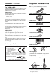
Supplied Accessories Precautions—Continued Make sure you have the following accessories: For British models Replacement and mounting of an AC plug on the power supply cord of this unit should be performed only by qualified service personnel.
Features Amplification • 90 watts minimum continuous power per channel, 8 ohm loads, 2 channels driven from 20 Hz to 20 kHz with a maximum total harmonic distortion of 0.08 % (FTC rating) • WRAT-Wide Range Amplifier Technology • Optimum Gain Volume Circuitry *1. Manufactured under license from Dolby Laboratories. “Dolby”, “Pro Logic” and the double-D symbol are registered trademarks of Dolby Laboratories. *2. “DTS” is a registered trademark of DTS, Inc. and “DTS-HD Master Audio” is a trademark of DTS, Inc.
Table of Contents Introduction Important Safety Instructions .................... 2 Precautions .................................................. 3 Supplied Accessories ................................. 4 Features........................................................ 5 Front & Rear Panels .................................... 7 Front Panel .................................................... 7 Display ........................................................... 9 Rear Panel ................................
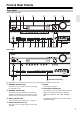
Front & Rear Panels Front Panel North American models 2 3 4 1 9 bk bl 5 bm 6 7 8 bn bo bp bq br bsbt ckclcm cn Other models co cp br (European models only) The page numbers in parentheses show where you can find the main explanation for each item. STANDBY/ON button (40) Display This button is used to set the AV receiver/AV ampliSee “Display” on page 9. fier to Standby or On.
Front & Rear Panels—Continued Arrow/TUNING/PRESET & ENTER buttons When the AM or FM input source is selected, the TUNING [ ] [ ] buttons are used to tune the tuner, and the PRESET [ ] [ ] buttons are used to select radio presets (see page 58) (TX-SR605 only). When the onscreen setup menus are used, they work as arrow buttons and are used to select and set items. The [ENTER] button is also used with the onscreen setup menus.
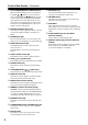
Front & Rear Panels—Continued Display 1 2 3 4 6 5 7 The page numbers in parentheses show where you can find the main explanation for each item. SLEEP indicator (56) This indicator lights up when the Sleep function has been set. MUTING indicator (56) This indicator flashes while the AV receiver/AV amplifier is muted. HDMI indicator This indicator lights up when the HDMI input is used.
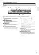
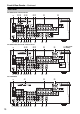
Front & Rear Panels—Continued Rear Panel TX-SR605 North American model 1 23 45 bl bm bn bo bpbqbr bs 67 bt 8 9 ck cl TX-SR605 other than North American model 1 45 bl bm bn bo bpbqbr bs 67 bt 8 9 ck cl TX-SA605/8560 1 4 bl bmcmbn bo bpbqbr bs 10 8 bt ck cl 9 (Only some bk models)
Front & Rear Panels—Continued The page numbers in parentheses show where you can find the main explanation for each item. DIGITAL IN OPTICAL 1, 2 and COAXIAL 1, 2 (4 CD IN These optical and coaxial digital audio inputs are This analog audio input is for connecting a CD for connecting components with optical or coaxial player’s analog audio output. digital audio outputs, such as CD and DVD players.
Remote Controller Installing the Batteries 1 To open the battery compartment, press the small hollow and slide off the cover. Aiming the Remote Controller To use the remote controller, point it at the AV receiver/AV amplifier’s remote control sensor, as shown below. Remote control sensor AV receiver/AV amplifier STANDBY indicator 2 3 Insert the two supplied batteries (AA/R6) in accordance with the polarity diagram inside the battery compartment.
Remote Controller—Continued Using the Remote Controller The remote controller can be used to control different components including the AV receiver/AV amplifier. The remote controller has a specific operating mode for use with each type of component. Modes are selected by using the six REMOTE MODE buttons. RECEIVER/TAPE Mode RECEIVER/TAPE mode is used to control the AV receiver/AV amplifier. It can also be used to control an Onkyo cassette recorder connected via .
Remote Controller—Continued For detailed information, see the pages in parentheses. (7 CINE FLTR button (69) Used with the CinemaFILTER function. ZONE 2 button (88) Used to select the input source for Zone 2. STANDBY/ON button (40) Sets the AV receiver/AV amplifier to Standby or On. INPUT SELECTOR buttons (54) Used to select the input sources. (8 L NIGHT button (69) Used with the Late Night function.
Remote Controller—Continued STANDBY/ON button DVD Mode Sets the DVD player to Standby or On. By default, the remote controller is set to control an Onkyo DVD player. To select your DVD player as the input source, press: Number buttons Used to enter title, chapter, and track numbers and times for locating specific points. DISC +/– button or Selects discs on a DVD changer. TOP MENU button Selects a DVD’s top menu.
Remote Controller—Continued STANDBY/ON button CD/MD/CDR/DOCK Mode Sets the component to Standby or On. By default, the remote controller is set to control an Onkyo CD player. To select the input source, press: Number buttons Used to enter track numbers and times for locating specific points on CD/MD players. DISC/ALBUM +/– button CD player MD or CD recorder Selects discs on a CD changer, or the next or previous album on an HDD-compatible component connected to an RI Dock.
About Home Theater Enjoying Home Theater Thanks to the AV receiver/AV amplifier’s superb capabilities, you can enjoy surround sound with a real sense of movement in your own home—just like being in a movie theater or concert hall. With DVDs you can enjoy DTS and Dolby Digital. With analog and digital TV you can enjoy Dolby Pro Logic IIx or Onkyo’s own DSP surround listening modes. Front left and right speakers These output the overall sound.
Connecting the AV Receiver/AV Amplifier AV Connection Color Coding About AV Connections • Before making any AV connections, read the manuals supplied with your other AV components. • Don’t connect the power cord until you’ve completed and double-checked all AV connections. Optical Digital Jacks The AV receiver/AV amplifier’s optical digital jacks have shutter-type covers that open when an optical plug is inserted and close when it’s removed. Push plugs in all the way.
Connecting the AV Receiver/AV Amplifier—Continued Connecting a Powered Subwoofer Connecting Your Speakers Speaker Configuration For the best surround sound experience, you should connect seven speakers and a powered subwoofer. The following table indicates the channels you should use depending on the number of speakers that you have.
Connecting the AV Receiver/AV Amplifier—Continued Speaker Connection Precautions Read the following before connecting your speakers: • North American models: Only connect speakers with an impedance of 6 ohms or higher. If you use speakers with a lower impedance, and use the amplifier at high volume levels for a long period of time, the built-in protection circuit may be activated. • Other models: You can connect speakers with an impedance of between 4 and 16 ohms.
Connecting the AV Receiver/AV Amplifier—Continued Bi-amping the Front Speakers The FRONT L/R and SURR BACK L/R terminal posts can be used with front speakers and surround back speakers respectively, or bi-amped to provide separate tweeter and woofer feeds for a pair of front speakers that support bi-amping, providing improved bass and treble performance. • When bi-amping is used, the AV receiver/AV amplifier is able to drive up to 5.1 speakers in the main room.
Connecting the AV Receiver/AV Amplifier—Continued Connecting Antenna (TX-SR605 only) This section explains how to connect the supplied indoor FM antenna and AM loop antenna, and how to connect commercially available outdoor FM and AM antennas. The AV receiver won’t pick up any radio signals without any antenna connected, so you must connect the antenna to use the tuner. AM antenna push terminals FM antenna connector Connecting the Indoor FM Antenna The supplied indoor FM antenna is for indoor use only.
Connecting the AV Receiver/AV Amplifier—Continued Connecting an Outdoor FM Antenna Connecting an Outdoor AM Antenna If you cannot achieve good reception with the supplied indoor FM antenna, try a commercially available outdoor FM antenna instead. If good reception cannot be achieved using the supplied AM loop antenna, an outdoor AM antenna can be used in addition to the loop antenna, as shown.
Connecting the AV Receiver/AV Amplifier—Continued Connecting Both Audio & Video By connecting both the audio and video outputs of your DVD player and other AV components to the AV receiver/AV amplifier, you can select both the audio and video simultaneously simply by selecting the appropriate input source on the AV receiver/AV amplifier. : Signal Flow Video Video Audio Audio TV, projector, etc. DVD player, etc.
Connecting the AV Receiver/AV Amplifier—Continued ■ HDMI Monitor Setting Set to No With the HDMI Monitor setting set to No (see page 47), video input signals flow through the AV receiver/AV amplifier as shown, with composite video and S-Video sources being upconverted for the component video output. Use this setting if you connect the AV receiver/AV amplifier’s COMPONENT VIDEO OUT to your TV. Composite video is upconverted to S-Video and S-Video is downconverted to composite video.
Connecting the AV Receiver/AV Amplifier—Continued Connecting Your TV or Projector Step 1: Video Connection Choose a video connection that matches your TV ( A , B , or C ), and then make the connection. Step 2: Audio Connection Choose an audio connection that matches your TV ( a , b , or c ), and then make the connection. • With connection a , you can listen to and record audio from your TV and listen in Zone 2. • To enjoy Dolby Digital and DTS, use connection b or c .
Connecting the AV Receiver/AV Amplifier—Continued Connecting a DVD Player Step 1: Video Connection Choose a video connection that matches your DVD player ( A , B , or C ), and then make the connection. You must connect the AV receiver/AV amplifier to your TV via the same type of connection. Step 2: Audio Connection Choose an audio connection that matches your DVD player ( a , b , or c ), and then make the connection. • With connection a , you can listen to and record audio from a DVD and listen in Zone 2.
Connecting the AV Receiver/AV Amplifier—Continued Hooking Up the Multichannel DVD Input If your DVD player supports multichannel audio formats such as DVD-Audio or SACD, and it has a multichannel analog audio output, you can connect it to the AV receiver/AV amplifier’s multichannel DVD input. Use a multichannel analog audio cable, or several normal audio cables, to connect the AV receiver/AV amplifier’s DVD IN FRONT L/R, CENTER, SURR L/R, SURR BACK L/R, and SUBWOOFER jacks to the 7.
Connecting the AV Receiver/AV Amplifier—Continued Connecting a VCR or DVD Recorder for Playback Hint! With this hookup, you can use your VCR’s tuner to listen to your favorite TV programs via the AV receiver/AV amplifier, useful if your TV has no audio outputs. Step 1: Video Connection Choose a video connection that matches your VCR or DVD recorder ( A , B , or C ), and then make the connection. You must connect the AV receiver/AV amplifier to your TV via the same type of connection.
Connecting the AV Receiver/AV Amplifier—Continued Connecting a VCR or DVD Recorder for Recording Step 1: Video Connection Choose a video connection that matches your VCR or DVD recorder ( A or B ), and then make the connection. The video source to be recorded must be connected to the AV receiver/AV amplifier via the same type of connection. Step 2: Audio Connection Make the audio connection a .
Connecting the AV Receiver/AV Amplifier—Continued Connecting a Satellite, Cable, Set-top box, or Other Video Source Hint! With this hookup, you can use your satellite or cable receiver to listen to your favorite TV programs via the AV receiver/AV amplifier, useful if your TV has no audio outputs. Step 1: Video Connection Choose a video connection that matches the video source ( A , B , or C ), and then make the connection.
Connecting the AV Receiver/AV Amplifier—Continued Connecting a Game Console Step 1: Video Connection Choose a video connection that matches the game console ( A , B , or C ), and then make the connection. If you use connection A , you must connect the AV receiver/AV amplifier to your TV with the same type of connection. Step 2: Audio Connection Choose an audio connection that matches the DVD player ( a , b , or c ), and then make the connection.
Connecting the AV Receiver/AV Amplifier—Continued Connecting a Camcorder or Other Device Step 1: Video Connection Choose a video connection that matches the camcorder ( A or B ), and then make the connection. Step 2: Audio Connection Choose an audio connection that matches the camcorder ( a or b ), and then make the connection. AUX INPUT DIGITAL b AUX INPUT L AUDIO R AUX INPUT VIDEO AUX INPUT S VIDEO A S VIDEO OUT a B VIDEO OUT L AUDIO R OUT OPTICAL OUT Camcorder, etc.
Connecting the AV Receiver/AV Amplifier—Continued Connecting Components with HDMI About HDMI Designed to meet the demands of digital TV, HDMI (High Definition Multimedia Interface) is a new digital interface standard for connecting TVs, projectors, DVD players, set-top boxes, and other video components. Until now, several separate video and audio cables have been required to connect AV components.
Connecting the AV Receiver/AV Amplifier—Continued Making HDMI Connections Step 1: Use HDMI cables to connect the AV receiver/AV amplifier’s HDMI jacks to your HDMI-compatible DVD player, TV, projector, and so on. Step 2: Assign each HDMI IN to an input selector in the HDMI Input Setup (see page 48). ■ Video Signals Digital video signals received by the HDMI IN jacks are normally output by the HDMI OUT for display on your TV.
Connecting the AV Receiver/AV Amplifier—Continued Connecting a CD Player or Turntable ■ CD Player or Turntable (MM) with Built-in Phono Preamp Step 1: Choose a connection that matches your CD player ( a , b , or c ). Use connection a for a turntable with a built-in phono preamp.
Connecting the AV Receiver/AV Amplifier—Continued Connecting an RI Dock ■ RI Dock with video Connect your RI Dock’s analog audio output jacks and S-Video output jack to the AV receiver/AV amplifier’s GAME/TV IN L/R jacks and GAME/TV IN S jack. (The example shown below is for connection with the DS-A1.) ■ RI Dock without video Connect your RI Dock’s analog audio output jacks to the AV receiver/AV amplifier’s TAPE IN L/R jacks.
Connecting the AV Receiver/AV Amplifier—Continued Connecting a Cassette, CDR, MiniDisc, or DAT Recorder Step 1: Choose a connection that matches the recorder ( a , b , or c ), and then make the connection. b c IN COAXIAL L IN 2 (CBL/SAT) R a TAPE OPTICAL a IN 1 (GAME/TV) L R TAPE Connect one or the other L COAXIAL OUT R OPTICAL OUT L AUDIO IN R AUDIO OUT Cassette, CDR, MD, etc. • With connection a , you can play and record and listen in Zone 2.
Connecting the AV Receiver/AV Amplifier—Continued Connecting Onkyo Components IN L Step 1: Make sure that each Onkyo component is connected to the AV receiver/AV amplifier with an analog audio cable (connection a in the hookup examples) (see pages 26 to 38). Step 2: Make the R CD FRONT REMOTE CONTROL L R DVD connection. Step 3: If you’re using an MD, CDR, or RI Dock, change the input display (see page 51).
Turning On the AV Receiver/AV Amplifier RECEIVER STANDBY/ON STANDBY indicator STANDBY/ON Connecting the Power Cord • Connect the AV receiver/AV amplifier’s power cord to a suitable wall outlet. Notes: • Before connecting the power cord, connect all of your speakers and AV components. • Turning on the AV receiver/AV amplifier may cause a momentary power surge that might interfere with other electrical equipment on the same circuit.
First Time Setup This section explains the settings that you need to make before using the AV receiver/AV amplifier for the very first time. Using Audyssey 2EQ Automatic Speaker Setup (Audyssey 2EQ) With the supplied speaker setup microphone, the Audyssey 2EQ function can measure the number of speakers connected, their sizes, crossover frequencies, and the distance from each speaker to the listening position and calculate the optimal speaker settings for your listening environment automatically.
First Time Setup—Continued 2 Put the speaker setup microphone at measurement point (page 41), and connect it to the SETUP MIC jack. Auto Speaker Setup 4 The speaker detect results appear. Auto Speaker Setup AUDYSSEY - - - - - SP Detect Result - - - - FL SL SBL C AUDYSSEY : : : : Yes Yes Yes No FR SR SBR SW : : : : Yes Yes Yes Yes Please place microphone at center Next Retry Cancel of listening area at ear height. “Yes” means that the speaker was detected.
First Time Setup—Continued 6 The following screen appears. Auto Speaker Setup 8 AUDYSSEY When the calculations are complete, the following screen appears. Auto Speaker Setup Please place microphone at left end 1. 2. 3. 4. 5. of listening area at ear height. AUDYSSEY Save Review SP Config Review SP Distance Review SP Level Cancel Push Enter : Next Move the speaker setup microphone to measurement point (page 41), then press [ENTER]. Audyssey 2EQ performs more measurements.
First Time Setup—Continued Error Messages Auto Speaker Setup While the automatic speaker setup is in progress, one of the following error messages may appear: - - - - - Speaker Detect Error - - - - - ❏ Ambient noise is too high FL SL SBL C Auto Speaker Setup AUDYSSEY : : : : Yes --No Yes FR SR SBR SW : : : : AUDYSSEY Yes Yes Yes --- Retry Cancel Ambient noise is too high. The right surround back speaker has been detected but the left surround back speaker hasn’t.
First Time Setup—Continued Reviewing the Results Changing the Speaker Settings Manually Use the Up and Down [ ]/[ ] buttons to select the settings that you want to review, and then press [ENTER]. Auto Speaker Setup AUDYSSEY Using a Powered Subwoofer Save Review SP Config Review SP Distance Review SP Level Cancel The options are: Review SP Config: Review the speaker configuration settings.
First Time Setup—Continued About the Onscreen Setup Menus The onscreen setup menus are displayed on the connected TV and provide a convenient way to change the AV receiver/ AV amplifier’s settings. Submenus p. 47 p. 50 1. 2. 3. 4. p. 70 p. 74 p. 51 Submenus 1. Input/Output Assign 1. 2. 3. 4. 5. 6. 7. 8. DVD VCR/DVR CBL/SAT GAME/TV AUX TAPE TUNER CD p. 81 6. Miscellaneous 2. Speaker Setup 1. 2. 3. 4. 5. p. 78 5.
First Time Setup—Continued 1 Press the [RECEIVER] button followed by the [SETUP] button. The main menu appears onscreen. 2 Use the Up and Down [ ]/[ ] buttons to select “1. Input/Output Assign,” and then press [ENTER]. The Input/Output Assign menu appears. 1 2, 3 2-4 1. Input/Output Assign 1, 5 1. 2. 3. 4.
First Time Setup—Continued 3 Video Input Setup HDMI Input Setup If you connect a video component to HDMI IN 1 or 2, you must assign that input to an input selector. For example, if you connect your DVD player to HDMI IN 1, you must assign HDMI IN 1 to the DVD input selector. If you’ve connected your TV to the AV receiver/AV amplifier with an HDMI cable, you can set the AV receiver/AV amplifier so that composite video, S-Video, and component video sources are upconverted* and output by the HDMI OUT.
First Time Setup—Continued Component Video Setup If you connect to a COMPONENT VIDEO IN, you must assign it to an input selector. For example, if you connect your DVD player to COMPONENT IN 3, you should assign it to the DVD input selector. If you want to output composite and S-Video sources from the COMPONENT VIDEO OUT, select “---,” as explained below. Input selector VIDEO IN jack DVD IN 1 VCR/DVR --- CBL/SAT --- GAME/TV --- AUX --- 3 1–3.
First Time Setup—Continued Digital Input Setup 4 Use the Up and Down [ ]/[ ] buttons to select an input selector, and use the Left and Right [ ]/[ ] buttons to select COAX 1, COAX 2, OPT 1, OPT 2, or - - - (analog). • An input selector that has been assigned to IN 1 or IN 2 in the “HDMI Input Setup” (see page 48) can be set to HDMI here. • There are no assignments for TUNER (TX-SR605 only). • AUX is used only for digital input from the front panel terminals.
First Time Setup—Continued Changing the Input Display If you connect an -capable Onkyo MiniDisc recorder, CD recorder, or RI Dock to the TAPE IN/OUT or GAME/TV IN jacks, for to work properly, you must change this setting. This setting can only be changed on the AV receiver/AV amplifier. 1, 2 1, 2 iPod photo: If you’re using an iPod photo with the DS-A1 Remote Interactive Dock, connect the DS-A1 to the GAME/TV IN jacks.
First Time Setup—Continued 4 5 6 Use the Up and Down [ ]/[ ] buttons to select “Speaker Impedance,” and then use the Left and Right [ ]/[ ] buttons to select: 4 ohms: Select if the impedance of any speaker is 4 ohms or more but less than 6. 6 ohms: Select if the impedances of all speakers are between 6 and 16 ohms. Use the Up and Down [ ]/[ ] buttons to select “Speakers Type,” and then use the Left and Right [ ]/[ ] buttons to select: Normal: Select this if you’ve connected your front speakers normally.
First Time Setup—Continued AM Frequency Step Setup (on some models) You must specify the AM frequency step used in your area. Note that when this setting is changed, all radio presets are deleted. 1 Press the [RECEIVER] button, followed by the [SETUP] button. The main menu appears onscreen. 2 Use the Up and Down [ ]/[ ] buttons to select “7. Hardware Setup,” and then press [ENTER]. The Hardware Setup menu appears. 7. Hardware Setup 1. 2. 3. 4. 5.
Basic Operations Selecting the Input Source This section explains how to select the input source (i.e., the AV component that you want to listen to or watch). MULTI CH 3 MULTI CH 1 1 3 1 1 AV receiver/ AV amplifier Remote controller To select the input source with the remote controller, press the [RECEIVER] button, and then use the INPUT SELECTOR buttons. or 2 3 Start playback on the source component.
Basic Operations—Continued Using the Multichannel DVD Input The multichannel DVD input is for connecting a component with a 7.1-channel analog audio output, such as a DVD-Audio or SACD-capable DVD player, or an MPEG decoder. See page 28 for hookup information. Press the [RECEIVER] button, followed by the [MULTI CH] button. The MULTI CH indicator appears on the display. Displaying Source Information You can display various information about the current input source as follows.
Basic Operations—Continued Press [RECEIVER] first DIMMER SLEEP MUTING Setting the Display Brightness You can adjust the brightness of the display. Press the [RECEIVER] button, and then press the [DIMMER] button repeatedly to select: dim, dimmer, or normal brightness. Alternatively, you can use the AV receiver’s [DIMMER] button (not European models). Using the Sleep Timer With the sleep timer, you can set the AV receiver/AV amplifier to turn off automatically after a specified period.
Listening to the Radio (TX-SR605 only) ■ Manual Tuning Mode Using the Tuner With the built-in tuner you can enjoy AM and FM radio stations. You can store your favorite stations as presets for quick selection. 1 Press the [TUNING MODE] button so that the AUTO indicator disappears from the display. 2 Press and hold the TUNING Up or Down [ ]/[ ] buttons. The frequency stops changing when you release the button. Press the buttons repeatedly to change the frequency one step at a time.
Listening to the Radio (TX-SR605 only)—Continued Presetting AM/FM Stations Selecting Presets PRESET 2, 4 3 You can store a combination of up to 40 of your favorite AM/FM radio stations as presets. 58 1 Tune into the AM/FM station that you want to store as a preset. 2 Press the [MEMORY] button. The preset number flashes. 3 While the preset number is flashing (about 8 seconds), use the PRESET [ ]/[ ] buttons to select a preset from 1 through 40.
Listening to the Radio (TX-SR605 only)—Continued Using RDS (European models only) RDS only works with European models and only in areas where RDS broadcasts are available. When tuned into an RDS station, the RDS indicator appears. RDS indicator ■ What is RDS? RDS stands for Radio Data System and is a method of transmitting data in FM radio signals. It was developed by the European Broadcasting Union (EBU) and is available in most European countries. Many FM stations use it these days.
Listening to the Radio (TX-SR605 only)—Continued Displaying Radio Text (RT) RT/PTY/TP 4 To start the search, press [ENTER]. The AV receiver searches until it finds a station of the type you specified, at which point it stops briefly before continuing with the search. 5 When a station you want to listen to is found, press [ENTER]. If no stations are found, the message “Not Found” appears. When tuned to an RDS station that’s broadcasting text information, the text can be displayed.
Using the Listening Modes Selecting Listening Modes Selecting with the Remote Controller See “About the Listening Modes” on page 66 for detailed information about the listening modes. • The Dolby Digital and DTS listening modes can only be selected if your DVD player is connected to the AV receiver/AV amplifier with a digital audio connection (coaxial or optical). • Listening mode availability depends on the format of the current input signal.
Using the Listening Modes—Continued Listening Modes Available for Each Source Format Analog and PCM Sources Multichannel PCM (32-192 kHz) PCM Source format 32-96 kHz Media 176.
Using the Listening Modes—Continued Dolby Digital, Dolby Digital Plus, and TrueHD Sources Dolby D Multichannel Source format */2 Media except */2 Multichannel 2ch 1/0, 1+1 */2 DVD, DTV, etc.
Using the Listening Modes—Continued DTS and DTS 96/24 Sources DTS, DTS 96/24 Source format Multichannel DTS Discrete/Matrix 2ch */2 Media 1/0 except */2 DVD, CD, etc. Listening mode DVD, CD, etc.
Using the Listening Modes—Continued DTS-HD High Resolution Audio and DTS-HD Master Audio Sources DTS-HD High Resolution Audio Source format Multichannel 2ch */2 Media 1/0 except *2 DTS-HD Master Audio*1 Multichannel Blu-ray, HD DVD Listening mode 2ch 1/0 Blu-ray, HD DVD Pure Audio (not North American models) ✔ ✔ ✔ ✔ ✔ ✔ ✔ Direct ✔ ✔ ✔ ✔ ✔ ✔ ✔ Stereo ✔ ✔ ✔ ✔ ✔ ✔ ✔ ✔ ✔ Multichannel Dolby D Dolby Digital Plus DTS, DTS 96/24 DTS Discrete/Matrix DTS-HD High Resolution Audio
Using the Listening Modes—Continued About the Listening Modes The AV receiver/AV amplifier’s listening modes can transform your listening room into a movie theater or concert hall, with high fidelity and stunning surround sound. The illustration shows which speakers are active in each listening mode with 7.1 channel speaker system.
Using the Listening Modes—Continued DTS-ES Matrix This mode is for use with DTS-ES Matrix soundtracks, which use a matrix-encoded back-channel for 6.1/7.1channel playback. Use it with DVDs that bear the DTSES logo, especially those with a DTS-ES Matrix soundtrack. Onkyo Original DSP Modes Mono Movie This mode is suitable for old movies and other mono sources.
Recording This section explains how to record the selected input source to a component with recording capability, and how to record audio and video from different sources. Notes: • The surround sound and DSP listening modes cannot be recorded. • Copy-protected DVDs cannot be recorded. • You cannot record from the DVD analog multichannel input. • Various restrictions apply to digital recording. Refer to the manuals supplied with your digital recording equipment for more details.
Advanced Operations Using the CinemaFILTER RECEIVER CH SEL L NIGHT With the CinemaFILTER, you can soften overly bright movie soundtracks, which are typically mixed for reproduction in a movie theater. CinemaFILTER can be used with the following listening modes: Dolby Digital, Dolby Digital EX, Dolby Pro Logic IIx Movie, Dolby Pro Logic II Movie, DTS, DTSES, DTS Neo:6 Cinema, DTS 96/24, and Neo:6. Note: The CinemaFILTER may not work when used with certain input sources.
Advanced Setup Speaker Setup 1 Press the [RECEIVER] button followed by the [SETUP] button. The main menu appears onscreen. 2 Use the Up and Down [ ]/[ ] buttons to select “2. Speaker Setup,” and then press [ENTER]. The Speaker Setup menu appears. Some of the settings in this section are set automatically by the Automatic Speaker Setup function (see page 41).
Advanced Setup—Continued 6 7 8 9 Use the Up and Down [ ]/[ ] buttons to select “Center,” and then use the Left and Right [ ]/ [ ] buttons to select a crossover frequency. If no center speaker is connected, select None. Note: If the Front setting in step 5 is set to anything other than Full Band, Full Band cannot be selected here. Use the Up and Down [ ]/[ ] buttons to select “Surround,” and then use the Left and Right [ ]/[ ] buttons to select a crossover frequency.
Advanced Setup—Continued Speaker Distance 3 This setting is set automatically by the Automatic Speaker Setup function (see page 41). Use the Up and Down [ ]/[ ] buttons to select “3. Speaker Distance,” and then press [ENTER]. The Speaker Distance menu appears. 2–3. Speaker Distance Here you can specify the distance from each speaker to the listening position so that the sound from each speaker arrives at the listener’s ears as the sound designer intended.
Advanced Setup—Continued Speaker Level Calibration 3 This setting is set automatically by the Automatic Speaker Setup function (see page 41). Here you can adjust the level of each speaker with the built-in test tone so that the volume of each speaker is the same at the listening position. Note: The speakers cannot be calibrated while the output of the AV receiver/AV amplifier is muted or while a pair of headphones is connected. 2–4.
Advanced Setup—Continued Equalizer Setting 3 This setting is set automatically by the Automatic Speaker Setup function (see page 41). Here you can adjust the EQ of individual speakers. To set the volume of individual speakers see page 73. Use the Up and Down [ ]/[ ] buttons to select “5. Equalizer Settings,” and then press [ENTER]. The Equalizer Settings menu appears. 2–5. Equalizer Settings Equalizer Off 1 4 Use the Left and Right [ ]/[ ] buttons to select: Off: Tone off, response flat.
Advanced Setup—Continued 7 8 Use the Up [ ] button to select “Channel,” and then use the Left and Right [ ]/[ ] buttons to select another speaker. Repeat step 6 and 7 for each speaker. Press the [SETUP] button. The setup menu closes. 2 7. Hardware Setup 1. 2. 3. 4. 5. 3 1 Press the [RECEIVER] button followed by the [SETUP] button. The main menu appears onscreen. Use the Up and Down [ ]/[ ] buttons to select “4. Analog Multich,” and then press [ENTER]. The Analog Multich menu appears.
Advanced Setup—Continued Audio Adjust Functions Here you can set listening mode-related settings and functions. 1 Press the [RECEIVER] button followed by the [SETUP] button. The main menu appears onscreen. The Audio Adjust functions are explained below. Tone Control Settings You can adjust the bass and treble for the front speakers, except when the Direct or Pure Audio (not North American models) listening mode is selected.
Advanced Setup—Continued PLIIx/Neo:6 Music Mode Settings Dolby EX Input Signal Setting These settings provide for playing any 2-channel digital source such as Dolby Digital, or 2-channel analog/PCM source in the PLIIx Music listening mode. ■ Dolby EX This setting determines how Dolby EX encoded signals are handled. This setting is unavailable if no surround back speakers are connected. This setting is effective with Dolby Digital and Dolby Digital Plus only.
Advanced Setup—Continued Assigning Listening Modes to Input Sources You can assign a default listening mode to each input source that will be selected automatically when you select each input source. For example, you can set the default listening mode to be used with Dolby Digital input signals. You can select other listening modes during playback, but the mode specified here will be resumed once the AV receiver/AV amplifier has been set to Standby.
Advanced Setup—Continued 5 When you’ve finished, press the [SETUP] button. The setup menu closes. 2 Use the Up and Down [ ]/[ ] buttons to select “4. Source Setup,” and then press [ENTER]. The Source Setup menu appears. 4. Source Setup DVD 1. IntelliVolume 2. A/V Sync Note: This procedure can also be performed on the AV receiver/AV amplifier by using its [SETUP] button, arrow buttons, and [ENTER] button.
Advanced Setup—Continued Correcting Sound and Picture Sync When using progressive scanning on your DVD player, you may find that the picture and sound are out of sync. With this setting, you can correct this by delaying the audio signals. You can set it from 0 to 100 milliseconds (msec) in 10 millisecond steps. 1 Press the [RECEIVER] button followed by the [SETUP] button. The main menu appears onscreen. 2 Use the Up and Down [ ]/[ ] buttons to select “4. Source Setup,” and then press [ENTER].
Advanced Setup—Continued 4 Volume Setup/OSD Setup This section explains the items on the Miscellaneous menu. Volume Setup 1 Use the Up and Down [ ]/[ ] buttons to select the settings, and use the Left and Right [ ]/ [ ] buttons to set them. Maximum Volume With this preference, you can prevent the volume being set too high by specifying a maximum volume level. The range is from 50 to 99. To specify no maximum volume, select Off. Press the [RECEIVER] button followed by the [SETUP] button.
Advanced Setup—Continued OSD Setup 1 4 Press the [RECEIVER] button followed by the [SETUP] button. The main menu appears onscreen. Use the Up and Down [ ]/[ ] buttons to select the settings, and use the Left and Right [ ]/ [ ] buttons to set them. These settings determine how the operation details are displayed. Immediate Display 2 This preference determines whether operation details are displayed onscreen when an AV receiver/AV amplifier function is adjusted. On: Displayed (default).
Advanced Setup—Continued . Changing the AV Receiver/AV HDMI Setup Amplifier’s ID 1 Press the [RECEIVER] button followed by the [SETUP] button. The main menu appears onscreen. 2 Use the Up and Down [ ]/[ ] buttons to select “7. Hardware Setup,” and then press [ENTER]. The Hardware Setup menu appears. 1 Press the [RECEIVER] button followed by the [SETUP] button. The main menu appears onscreen. 2 Use the Up and Down [ ]/[ ] buttons to select “7. Hardware Setup,” and then press [ENTER].
Advanced Setup—Continued HDMI Audio Out This preference determines whether audio received at the HDMI IN is output by the HDMI OUT. You may want to turn this preference on if your TV is connected to the HDMI OUT and you want to listen to the audio from a component that’s connected to an HDMI IN, through your TV’s speakers. Normally, this should be set to Off. Off: HDMI audio is not output (default). On: HDMI audio is output.
Advanced Setup—Continued Lock Setup Digital Input Signal Formats 1 Press the [RECEIVER] button followed by the [SETUP] button. The main menu appears onscreen. 2 Use the Up and Down [ ]/[ ] buttons to select “8. Lock Setup,” and then press [ENTER]. The Lock Setup menu appears. The digital input signal formats are available only for the input sources that you have assigned a digital input jack; otherwise you will see “Analog” indicated on the screen (see page 50).
Advanced Setup—Continued Changing the Remote Controller’s ID If several Onkyo components are used in the same room, the remote controller’s control codes may overlap with those of another component. To differentiate the remote controller’s control codes, you can change its ID to another number. Note: If you change the remote controller’s ID, be sure to set the same ID on both the remote controller and AV receiver/AV amplifier (see “Changing the AV Receiver/ AV Amplifier’s ID” on page 83).
Zone 2 North American models Connecting Zone 2 With the Zone 2 function, you can enjoy one input source in the main room and a different source in another room. There are two connection methods: using a receiver/integrated amp in Zone 2 or using only a pair of speakers in Zone 2. Note: For speaker connections and related cautions, see page 20. 1 Strip 3/8" (10 mm) of insulation from the ends of the speaker cables, and twist the bare wires tightly, as shown.
Zone 2—Continued 5 Setting the Powered Zone 2 Press the [SETUP] button. The setup menu closes. To use Zone 2, you must make this setting. It enables the speakers connected to the ZONE 2 SPEAKERS terminals so that they produce sound when Zone 2 is used. 1 Press the [RECEIVER] button followed by the [SETUP] button. The main menu appears onscreen. Note: This procedure can also be performed on the AV receiver/AV amplifier by using its [SETUP] button, arrow buttons, and [ENTER] button.
Zone 2—Continued Controlling Zone 2 with the Remote Controller Adjusting the Volume for Zone 2 ZONE 2 LEVEL , ZONE 2 STANDBY/ON INPUT SELECTOR Remote controller On the remote controller, press the [ZONE 2] button, and then use the [LEVEL–] and [LEVEL+] buttons. AV receiver/ AV amplifier On the AV receiver/AV amplifier, use the ZONE 2 LEVEL [ ]/[ ] buttons. LEVEL –/+ Note: • To control Zone 2, you must press the remote controller’s [ZONE 2] button first.
Controlling Other Components You can use the AV receiver/AV amplifier’s remote controller (RC-682M) to control your other AV components, including those made by other manufacturers. This section explains how to enter the necessary remote control code for the component that you want to control (e.g., DVD player, TV, or VCR). 2 While holding down the REMOTE MODE button that you want to set, press the [DISPLAY] button for 3 seconds. The REMOTE MODE button lights up.
Controlling Other Components—Continued Remote Control Codes for Onkyo Components Connected via Onkyo components that are connected via are controlled by pointing the remote controller at the AV receiver/AV amplifier, not the component. This allows you to control components that are out of view, in a rack, for example. 1 Make sure the Onkyo component is connected with an cable and an analog audio cable (RCA). See page 39 for details.
Controlling Other Components—Continued To control another component, point the remote controller at it and use the buttons explained below. (You must select the appropriate remote control mode first.) With some AV components, certain buttons may not work as expected, and some may not work at all.
Specifications Amplifier Section General Rated Output Power (FTC) All channels: 90 watts minimum continuous power per channel, 8 ohm loads, 2 channels driven from 20 Hz to 20 kHz, with a maximum total harmonic distortion of 0.08% 105/110 watts minimum continuous power per channel, 8 ohm loads, 2 channels driven at 1 kHz, with a maximum total harmonic distortion of 0.7/0.9% 110 watts minimum continuous power per channel, 6 ohm loads, 2 channels driven at 1 kHz with a maximum total harmonic distortion of 0.
Troubleshooting If you have any trouble using the AV receiver/AV amplifier, look for a solution in this section. If you can’t resolve the issue yourself, contact your Onkyo dealer. If you can’t resolve the issue yourself, try resetting the AV receiver/AV amplifier before contacting your Onkyo dealer. To reset the AV receiver/AV amplifier to its factory defaults, turn it on and, while holding down the [VCR/DVR] button, press the [STANDBY/ON] button.
Troubleshooting—Continued The surround back speakers produce no sound • The surround back speakers are not used with all listening modes. Select another listening mode (page 66). • Not much sound may be produced by the surround back speakers with some sources. • Make sure the speakers are configured correctly (page 70). The DVD analog multichannel input doesn’t work • Check the DVD analog multichannel input connections (page 28).
Troubleshooting—Continued • If the video source is connected to a component video input, your TV must be connected to the COMPONENT VIDEO OUT or HDMI OUT (page 25). • If the video source is connected to an HDMI input, your TV must be connected to the HDMI OUT (page 25). • While the Pure Audio listening mode (not North American models) is selected, the video circuitry is turned off and only video signals input through HDMI IN can be output.
Troubleshooting—Continued Recording Can’t record • On your recorder, make sure the correct input is selected (e.g., digital or analog). • When the Pure Audio listening mode (not North American models) is selected, recording is not possible because no video signals are output. Select another listening mode. The following settings can be made for the component video, S-Video, and composite video inputs You must use the buttons on the unit to make these settings. 1.
MEMO 98
MEMO 99
Sales & Product Planning Div. : 2-1, Nisshin-cho, Neyagawa-shi, OSAKA 572-8540, JAPAN Tel: 072-831-8023 Fax: 072-831-8124 ONKYO U.S.A. CORPORATION 18 Park Way, Upper Saddle River, N.J. 07458, U.S.A. Tel: 201-785-2600 Fax: 201-785-2650 http://www.us.onkyo.com/ ONKYO EUROPE ELECTRONICS GmbH Liegnitzerstrasse 6, 82194 Groebenzell, GERMANY Tel: +49-8142-4401-0 Fax: +49-8142-4401-555 http://www.eu.onkyo.