Contents Introduction ..................................... 2 AV Receiver TX-SR573 Connections .................................. 15 Turning On & First Time Setup..... 30 Instruction Manual Basic Operation Playing your AV components ....... 34 Listening to AM/FM Stations........ 36 Listening to XM Satellite Radio..... 37 Using the Listening Modes .......... 44 Thank you for purchasing an Onkyo AV receiver. Please read this manual thoroughly before making connections and plugging in the unit.
WARNING: TO REDUCE THE RISK OF FIRE OR ELECTRIC SHOCK, DO NOT EXPOSE THIS APPARATUS TO RAIN OR MOISTURE. CAUTION: TO REDUCE THE RISK OF ELECTRIC SHOCK, DO NOT REMOVE COVER (OR BACK). NO USER-SERVICEABLE PARTS INSIDE. REFER SERVICING TO QUALIFIED SERVICE PERSONNEL.
Precautions 1. Recording Copyright—Unless it’s for personal use only, recording copyrighted material is illegal without the permission of the copyright holder. 2. AC Fuse—The AC fuse inside the unit is not userserviceable. If you cannot turn on the unit, contact your Onkyo dealer. 3. Care—Occasionally you should dust the unit all over with a soft cloth. For stubborn stains, use a soft cloth dampened with a weak solution of mild detergent and water. Dry the unit immediately afterwards with a clean cloth.
Supplied Accessories Features Make sure you have the following accessories: Amp Remote controller & three batteries (AA/R6) • 7-channel amplifier • 75 watts per channel min. RMS at 8 Ω, 2 channels driven from 20 Hz to 20 kHz with no more than 0.
Contents Introduction Important Safety Instructions ....................2 Precautions .................................................3 Supplied Accessories.................................4 Features .......................................................4 Front & Rear Panels....................................6 Remote Controller.......................................9 Connection Connecting Your Speakers ......................15 Connecting Antenna .................................
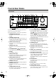
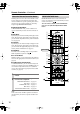
Front & Rear Panels Front Panel 1 2 3 4 5 6 78 9J K L M TUNING / PRESET MASTER VOLUME STANDBY/ON ENTER STANDBY A SPEAKERS B + TONE STEREO LISTENING MODE DISPLAY DIGITAL INPUT DIMMER RETURN MEMORY TUNING MODE SETUP CLEAR VIDEO 3 INPUT PHONES MULTl CH DVD VIDEO 1 VIDEO 2 VIDEO 3 TAPE TUNER VIDEO CD L AUDIO R VCR N OP Q The actual front panel has various logos printed on it. They are not shown here for clarity. For detailed information, see the pages in parentheses.
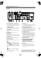
Front & Rear Panels—Continued Display 1 2 3 5 4 6 For detailed information, see the pages in parentheses. 1 A & B speaker indicators (34) Indicator A lights up when speaker set A is on. Indicator B lights up when speaker set B is on. 2 MUTING indicator (42) This indicator flashes when the AV receiver is muted. 3 Source/listening mode indicators (46) These indicators show the currently selected listening mode and digital audio format.
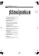
Front & Rear Panels—Continued Rear Panel 1 8 B 9 J 3 4 56 7 K L A DIGITAL IN OPTICAL 1, 2, 3 & COAXIAL These optical and coaxial jacks can be used to connect a CD or DVD player and other components with digital audio outputs. B COMPONENT VIDEO A DVD player, TV, or other component that supports component video can be connected here. C AM ANTENNA These push terminals are for connecting an AM antenna. D FM ANTENNA This jack is for connecting an FM antenna.
Remote Controller Installing the Batteries 1 To open the battery compartment, press the small hollow and slide open the cover. Using the Remote Controller To use the remote controller, point it at the AV receiver’s remote control sensor, as shown below. Remote control sensor AV receiver STANDBY indicator 2 3 Insert the three supplied batteries (AA/R6) in accordance with the polarity diagram inside the battery compartment. Slide the cover shut.
Remote Controller—Continued About the Remote Controller Modes Including the AV receiver, the remote controller can be used to control up to nine different components. The remote controller has a specific operating mode for use with each type of component. Modes are selected by using the eight REMOTE MODE buttons. ■ RECEIVER/TAPE Mode In RECEIVER/TAPE mode, you can control the AV receiver and an Onkyo cassette recorder connected via . RECEIVER/TAPE Mode RECEIVER/TAPE mode is used to control the AV receiver.
Remote Controller—Continued For detailed information, see the pages in parentheses. N SLEEP button (43) This button is used to set the Sleep function. A STANDBY button (30) O MENU button (38) This button is used to set the AV receiver to Standby. B ON button (30) This button is used to turn on the AV receiver. C INPUT SELECTOR buttons (34) These buttons are used to select the input sources.
Remote Controller—Continued D TOP MENU button DVD Mode This button is used to select a DVD’s top menu. To set the remote controller to DVD mode, press the [DVD] REMOTE MODE button. E Arrow [ ]/[ ]/[ ]/[ ] & ENTER buttons These buttons are used to navigate DVD menus and the DVD player’s onscreen setup menus. F DISC +/– button This button selects discs on a DVD changer.
Remote Controller—Continued A STANDBY button CD, MD & CDR Modes To control an Onkyo CD player, or a CD/MD recorder made by another manufacturer, press the [CD] REMOTE MODE button to select the CD remote controller mode. To control an Onkyo MD recorder or CD recorder, press the [MD] or [CDR] REMOTE MODE button to select the MD or CDR remote controller mode.
Remote Controller—Continued B ON button* HDD Mode HDD mode is for controlling Onkyo’s next generation HDD-compatible components. As of 2005, it can be used with the Onkyo DS-A1 Remote Interactive Dock and Apple iPod connected via . When Using the DS-A1: • Connect the DS-A1 to the TAPE IN or VIDEO 2 IN jacks. • Set the DS-A1’s RI MODE switch to HDD. • Set the AV receiver’s input display to HDD (see page 31). • Refer to the DS-A1’s instruction manual. This button turns on the HDD-compatible component.
Connecting Your Speakers About Speakers You can use two sets of speakers with the AV receiver: speaker set A and speaker set B. Speaker set A should be installed in your main listening room, and can be used with Dolby Digital and DTS sources. To get the best surround sound experience, each speaker must be positioned at a specific location within the room, as shown in the following illustration. Note that while speaker set B is on, speaker set A is reduced to 5.1-channel playback.
Connecting Your Speakers—Continued How Many Speakers? Speaker Connection Precautions For the best surround-sound experience, you should connect seven speakers and a powered subwoofer. The following table shows which channels you should use based on the number of speakers that you have.
Connecting Your Speakers—Continued Connecting Speaker Set A Connecting Speaker Set B 1 Strip 5/8" (15 mm) of insulation from the ends of the speaker cables, and twist the bare wires tightly, as shown. 2 Unscrew the terminal. Fully insert the bare wires. Make sure that the bare wire is touching the inside of the pole. Screw the terminal tight. 5/8" (15 mm) 1 Strip 3/8" (10 mm) of insulation from the ends of the speaker cables, and twist the bare wires tightly, as shown.
Connecting Antenna This section explains how to connect the supplied indoor FM antenna and AM loop antenna, and how to connect commercially available outdoor FM and AM antennas. The AV receiver won’t pick up any radio signals without any antenna connected, so you must connect the antenna to use the tuner. AM antenna push terminals FM antenna jack Connecting the Indoor FM Antenna The supplied indoor FM antenna is for indoor use only. 1 Attach the FM antenna, as shown.
Connecting Antenna—Continued Connecting an Outdoor FM Antenna Connecting an Outdoor AM Antenna If you cannot achieve good reception with the supplied indoor FM antenna, try a commercially available outdoor FM antenna instead. If good reception cannot be achieved using the supplied AM loop antenna, an outdoor AM antenna can be used in addition to the loop antenna, as shown.
Connecting Your Components AV Connection Color Coding About AV Connections RCA-type AV connections are usually color coded: red, white, and yellow. Use red plugs to connect right-channel audio inputs and outputs (typically labeled “R”). Use white plugs to connect left-channel audio inputs and outputs (typically labeled “L”). And use yellow plugs to connect composite video inputs and outputs. • Before making any AV connections, read the manuals supplied with your other AV components.
Connecting Your Components—Continued Connecting Audio & Video Signals to the AV Receiver By connecting both the audio and video outputs of your DVD player and other AV components to the AV receiver, you can switch the audio and video signals simultaneously simply by changing the input source on the AV receiver. : Signal Flow Video Video Audio Audio TV, projector, etc. DVD player, etc.
Connecting Your Components—Continued Connecting a TV or Projector Step 1: Video Connection Choose a connection that matches your TV ( A , B , or C ), and then make the connection. A COMPONENT VIDEO MONITOR OUT V C MONITOR OUT S B Y PB PR COMPONENT VIDEO IN Y PB TV, projector, etc.
Connecting Your Components—Continued Connecting a DVD player Step 1: Video Connection Choose a connection that matches your DVD player ( A , B , or C ), and then make the connection. A COMPONENT VIDEO DVD V C S B DVD IN Y IN PB DVD Your TV must be connected to the AV receiver via the same type of connection.
Connecting Your Components—Continued Connecting a VCR or DVD Recorder for Playback In addition to video playback, with this hookup example, you can use your VCR’s tuner to listen to your favorite TV programs via the AV receiver. This is useful if your TV has no audio outputs. Step 1: Video Connection Choose a connection that matches your VCR or DVD recorder ( A , B , or C ), and then make the connection. Your TV must be connected to the AV receiver via the same type of connection.
Connecting Your Components—Continued Connecting a VCR or DVD Recorder for Recording Step 1: Choose a video connection that matches your VCR or DVD recorder ( A or B ), and make the connection. The video source that you want to record must be connected to the AV receiver via the same type of connection. Step 2: Make audio connection a .
Connecting Your Components—Continued Connecting a Satellite, Cable, Set-top Box, or Other Video Source Step 1: Video Connection Choose a connection that matches the video source ( A , B , or C ), and then make the connection. A V C S B VIDEO 2 COMPONENT VIDEO VIDEO 2 IN Y IN PB VIDEO 2 Your TV must be connected to the AV receiver via the same type of connection. PR IN COMPONENT VIDEO OUT Y S VIDEO OUT PB PR Satellite, cable, set-top box, etc.
Connecting Your Components—Continued Connecting a CD Player or Turntable ■ CD Player or Turntable with Built-in Phono Preamp Step 1: Choose a connection that matches your CD player ( a , b , or c ), and then make the connection. Use connection a for a turntable with a built-in phono preamp.
Connecting Your Components—Continued Connecting a Cassette, CDR, MiniDisc, or DAT Recorder Step 1: Choose a connection that matches the recorder ( a , b , or c ), and then make the connection. b Connect one or the other DIGITAL IN COAXIAL c OUT IN L a OPTICAL 3 R TAPE L L R R IN OUT REC PLAY COAXIAL OUT OPTICAL OUT Cassette recorder, CDR, etc. • With connection a , you can play and record with the recorder and listen via speaker set B.
Connecting Your Components—Continued Connecting -capable Onkyo Components Step 1: Make sure that the Onkyo component is connected to the AV receiver with an analog audio cable (RCA). Step 2: Make the With connection. (Remote Interactive) you can use the following special functions: Auto Power On/Standby When you start playback on a component connected via , if the AV receiver is on Standby, it will automatically turn on and select that component as the input source.
Turning On the AV Receiver STANDBY/ON STANDBY indicator STANDBY ON STANDBY V1 V2 V3 1 2 3 + TV ON TUNING / PRESET MASTER VOLUME INPUT I MULTI CH DVD T V CH 4 5 6 - CD TAPE TUNER 7 8 9 +10 0 CLEAR STANDBY/ON ENTER STANDBY A SPEAKERS B + TONE STEREO LISTENING MODE DISPLAY DIGITAL INPUT DIMMER MEMORY TUNING MODE T V VOL SETUP RETURN CLEAR 11 --/ --- 10 INPUT SELECTOR VIDEO 3 INPUT PHONES MULTl CH DVD VIDEO 1 VIDEO 2 VIDEO 3 TAPE TUNER CD VIDEO L AUDIO R
First Time Setup Assigning Digital Inputs to Sources 2, 3 TUNING / PRESET MASTER VOLUME STANDBY/ON ENTER STANDBY A SPEAKERS B + TONE STEREO LISTENING MODE DISPLAY DIGITAL INPUT DIMMER MEMORY TUNING MODE RETURN SETUP CLEAR VIDEO 3 INPUT PHONES MULTl CH DVD VIDEO 1 VIDEO 2 VIDEO 3 TAPE TUNER CD VIDEO L AUDIO R Changing the Input Display If you connect an -capable Onkyo MiniDisc recorder, CD recorder, or next generation HDD-compatible component to the TAPE IN/OUT or VIDEO 2 IN jack
First Time Setup—Continued 2 ENTER ON STANDBY TV INPUT I V1 V2 1 2 3 + MULTI CH DVD T V CH - Use the Up and Down [ ]/[ ] buttons to select “1. Speaker Config,” and then press the [ENTER] button.
First Time Setup—Continued 6 ENTER ENTER Use the Down [ ] button to select “Surround,” and then use the Left and Right [ ]/[ ] buttons to select Small, Large, or None. Small: Select if the surround speakers are small. Large: Select if the surround speakers are large. None: Select if no surround speakers are connected. Note: • If the Front setting in step 4 is set to Small, the Large option cannot be selected.
Playing Your AV Components Basic AV Receiver Operation ON STANDBY V1 V2 V3 1 2 3 + TV INPUT I MULTI CH DVD T V CH 4 5 6 - CD TAPE TUNER 7 8 9 +10 0 CLEAR 1 2 4 DISPLAY T V VOL 11 --/ --- 10 INPUT SELECTOR 12 MACRO 1 TUNING / PRESET 2 3 MASTER VOLUME 1 STANDBY/ON ENTER REMOTE MODE RECEIVER TV STANDBY DVD CD HDD VCR CABLE SAT CDR MD TAPE/AMP SLEEP DIMMER A SPEAKERS B + TONE STEREO LISTENING MODE DISPLAY DIGITAL INPUT DIMMER MEMORY TUNING MODE RETURN
Playing Your AV Components—Continued Displaying Source Information You can display various information about the current input source as follows. ON STANDBY V1 V2 V3 1 2 3 + TV INPUT I MULTI CH DVD T V CH 4 5 6 - CD TAPE TUNER 7 8 9 +10 0 CLEAR MULTI CH RECEIVER T V VOL 11 --/--- 10 INPUT SELECTOR 12 MACRO 1 2 Press the [RECEIVER] REMOTE MODE button, and then press the [DISPLAY] button repeatedly to cycle through the available information.
Listening to the Radio ■ Manual Tuning Mode Listening to AM/FM Stations 1 TUNING MODE TUNING TUNING / PRESET Press the [TUNING MODE] button so that the AUTO indicator disappears from the display. TUNING MODE MASTER VOLUME STANDBY/ON ENTER 2 STANDBY A SPEAKERS B + TONE STEREO LISTENING MODE DISPLAY DIGITAL INPUT DIMMER MEMORY TUNING MODE RETURN SETUP Press and hold the TUNING Up or Down [ ]/[ ] button. The frequency stops changing when you release the button.
Listening to the Radio—Continued Listening to XM Satellite Radio® What’s XM Satellite Radio? There is a world beyond AM and FM. It is XM Satellite Radio. XM offers more than 150 digital channels of audio entertainment, including 100% commercial-free music channels, in the top markets in the U.S. Note: An XM Connect-and-Play™ antenna and monthly subscription are required to receive XM Satellite Radio. Visit www.xmradio.com for details.
Listening to the Radio—Continued ■ Category Search Mode Selecting XM Radio Channels There are two modes for selecting XM radio channels: Channel Search mode, which allows you to select any channel. Category Search mode, which allows you to select channels by category. ON STANDBY V1 V2 V3 1 2 3 + 1 RECEIVER TUNER 9 TV INPUT I MULTI CH DVD T V CH 4 5 6 - CD TAPE TUNER 7 8 9 +10 0 CLEAR 2 Press the [MENU] button to select “Category Search” mode.
Listening to the Radio—Continued 11 --/ --- 10 INPUT SELECTOR 12 MACRO 1 DISPLAY 2 REMOTE MODE / RECEIVER RECEIVER DVD CD HDD VCR CABLE SAT CDR MD TAPE/AMP TV TUNING / PRESET 3 MASTER VOLUME SLEEP DIMMER STANDBY/ON P TO ENTER M EN U MEN U + STANDBY CH A SPEAKERS B + TONE STEREO LISTENING MODE DISPLAY DIGITAL INPUT DIMMER MEMORY TUNING MODE RETURN DISC ALBUM SETUP ENTER VOL CLEAR - VIDEO 3 INPUT PHONES MULTl CH DVD VIDEO 1 VIDEO 2 VIDEO 3 TAPE TUNER CD VID
Listening to the Radio—Continued / XM Radio Messages , ENTER TUNING / PRESET The following messages may appear while using XM radio. MASTER VOLUME STANDBY/ON ENTER STANDBY A SPEAKERS B + TONE STEREO LISTENING MODE DISPLAY DIGITAL INPUT DIMMER RETURN MEMORY TUNING MODE SETUP CLEAR VIDEO 3 INPUT PHONES MULTl CH DVD VIDEO 1 VIDEO 2 VIDEO 3 TAPE TUNER CD VIDEO L AUDIO R VCR SETUP The XM antenna is not connected properly. Check the antenna.
Listening to the Radio—Continued Selecting Presets Presetting AM/FM Stations & XM Channels ON 1 STANDBY TV INPUT I 2, 4 3 V1 V2 V3 TUNING / PRESET 2 3 + MULTI CH DVD T V CH 1 MASTER VOLUME STANDBY/ON ENTER STANDBY TUNING / PRESET - 4 5 6 CD TAPE TUNER MASTER VOLUME A SPEAKERS B + TONE LISTENING MODE STEREO DISPLAY DIGITAL INPUT 7 STANDBY/ON DIMMER 8 RETURN MEMORY TUNING MODE 9 SETUP CLEAR MULTl CH DVD VIDEO 1 VIDEO 2 VIDEO 3 +10 STANDBY + TONE STEREO
Common Functions This chapter explains functions that can be used with any input source. Adjusting the Bass & Treble You can adjust the bass and treble for the front speakers (except when the Direct listening mode is selected). ON STANDBY V1 1 TV V2 V3 2 3 + MULTI CH DVD T V CH 4 5 6 - CD TAPE TUNER 7 8 9 +10 0 CLEAR 1 Press the AV receiver’s [TONE] button repeatedly to select either Bass or Treble.
Common Functions—Continued Using the Sleep Timer Adjusting Speaker Levels With the sleep timer, you can set the AV receiver so that it turns off automatically after a specified period. SLEEP Press the remote controller’s [SLEEP] button repeatedly to select the required sleep time. You can set the sleep time from 90 to 10 minutes in 10 minute steps. The SLEEP indicator appears on the display when the sleep timer has been set, as shown.
Using the Listening Modes Selecting with the Remote Controller Selecting the Listening Modes CDR MD SLEEP DIMMER For a description of each listening mode, see “About the Listening Modes” on page 46. P TO U M EN MEN U + CH DISC ALBUM • The Dolby Digital and DTS listening modes can only be selected if your DVD player is connected to the AV receiver with a digital audio connection (coaxial or optical). • Listening mode availability depends on the format of the current input signal.
Using the Listening Modes—Continued The following table shows which listening modes can be used with each input signal format. DTS/DTS 96/24*2 Dolby D Source Format Analog, PCM*1 3/2.1 2/2.1 CD, TV, VHS, MD, turntable, radio, cassette, DTV, etc. Listening mode 2/0 1/0,1+1 (Stereo) Other 3/2.1 DVD, DTV, etc. DTS-ES 2/0 (Stereo) Discrete Matrix DVD, CD, etc.
Using the Listening Modes—Continued About the Listening Modes With its surround-sound decoders and DSP modes, the AV receiver can transform your home listening room into a movie theater or concert hall. The AV receiver’s surround indicators show which speakers are active in each listening mode. Front left Center Front right Surround left Surround back left/ right Surround right Subwoofer Direct In this mode, the input source is output as it is, with minimal processing for a faithful sound.
Using the Listening Modes—Continued Onkyo Original DSP Modes Mono Movie Suitable for old movies and other mono sources. The center speaker outputs the sound as it is, while reverb is applied to the sound output by the other speakers, providing presence. Orchestra Suitable for classical or operatic music. The surround channels are emphasized in order to widen the stereo image. In addition, it simulates the natural reverberation of a large hall.
Using the Listening Modes—Continued Using the CinemaFILTER ON STANDBY V1 V2 V3 1 2 3 + With the CinemaFILTER, you can soften overly bright movie soundtracks, which are typically mixed for reproduction in a movie theater. CinemaFILTER can be used with the following listening modes: Dolby Digital, Dolby Digital EX, Dolby Pro Logic II Movie, Dolby Pro Logic IIx Movie, DTS, DTS-ES, DTS Neo:6 Cinema, DTS 96/24, DTS+Neo:6, and DTS+Dolby EX.
Using the Listening Modes—Continued 3 ENTER Use the Left and Right [ ]/[ ] buttons to change the setting. Press the Down [ ] button to select the next setting. ENTER 4 Repeat step 3 for the other settings. 5 Press the [SETUP] button. Setup closes. Higher settings move the sound field forward. Lower settings move it backward. If the stereo image feels too wide, or there’s too much surround sound, move the sound field forward to improve the balance.
Recording This section explains how to record the selected input source to a component with recording capability, and how to record audio and video from different sources. Recording the Input Source You can only record to a component that is connected to the TAPE OUT or VIDEO 1 OUT jacks. See pages 20–29 for information on connecting your AV components.
Advanced Setup Advanced Speaker Settings The advanced speaker settings cannot be changed while headphones are connected, speaker set B is on, or the multichannel DVD input is selected. Crossover Frequency To get the best bass performance from your speaker system, you need to set the crossover frequency according to the size and frequency response of your subwoofer and other speakers. Speaker cone diameter Crossover frequency Over 8 in. (20 cm) 60Hz 6-1/2 to 8 in. (16–20 cm) 80Hz 5-1/4 to 6-1/2 in.
Advanced Setup—Continued Speaker Distance To get the best from surround sound, it’s important that the sound from each speaker reaches the listener at the same time. To achieve this, you need to specify the distance from each speaker to the listening position. 1 2 Measure and make a note of the distance from each speaker to the listening position. RECEIVER Press the [RECEIVER] REMOTE MODE button, followed by the [SETUP] button. Notes: • The Center and Subwoofer distances can be set up to 5 ft. (1.
Advanced Setup—Continued 4 ENTER Use the Left and Right [ ]/[ ] buttons to adjust the speaker level, and use the Down [ ] button to select the next speaker. The levels can be adjusted from –12 to +12 dB in 1 dB steps (–15 to +12 dB for the subwoofer). Digital Signal Formats The following table shows the display indicator for each digital signal format. Format Display Dolby Digital DTS PCM PCM ENTER 5 Repeat step 4 so that the level of the test tone coming from each speaker is the same.
Controlling Other Components You can use the AV receiver’s remote controller (RC-632M) to control your other AV components, including those made by other manufacturers. This section explains how to: • Enter the remote control code for a component that you want to control (e.g., DVD, TV, VCR). • Learn commands directly from another component’s remote controller (see page 57). • Program the MACRO buttons to perform a sequence of up to eight actions (see page 58).
Controlling Other Components—Continued Remote Control Codes for Onkyo Components Connected via Onkyo components that are connected via are controlled by pointing the remote controller at the AV receiver, not the component. This allows you to control components that are out of view, in a rack, for example. 1 2 Make sure the Onkyo component is connected with an cable and an analog audio cable (RCA). See page 29 for details.
Controlling Other Components—Continued To control another component, point the remote controller at it and use the buttons explained below. (You must select the appropriate remote control mode first.) With some AV components, certain buttons may not work as expected, and some may not work at all.
Controlling Other Components—Continued 3 PO D C PE TA C D IS D C -1 D VD EO VID D EP E SL ER W CH TI- T UL PU M IN RE SUOD M O Remote indicator ER About 2 to 6 inches (5–15 cm) O N R O T TO H SE C P ER E LE R N PR SE E TU T UN PU T IN P U PE O R TA G VD D -2 EO VID H C SE L VE ST E TEON T L U M TIN G VO M LU E R The AV receiver’s remote controller can receive and learn commands from other remote controllers.
Controlling Other Components—Continued Using Macros 1 You can program the remote controller’s MACRO buttons to perform a sequence of actions. Example: To play a CD, you typically need to perform the following actions: 1. Press the [RECEIVER] REMOTE MODE button to select Receiver mode. 2. Press the [ON] button to turn on the AV receiver. 3. Press the [CD] INPUT SELECTOR button to select the CD input source. 4. Press the REMOTE MODE [CD] button to select the CD remote controller mode. 5.
Troubleshooting If you have any trouble using the AV receiver, look for a solution in this section. If you can’t resolve the issue yourself, contact your Onkyo dealer. Power Can’t turn on the AV receiver • Make sure that the power cord is plugged into the wall outlet properly. • Unplug the power cord from the wall outlet, wait 5 seconds or more, then plug it in again. The AV receiver turns off as soon as it’s turned on • The amp protection circuit has been activated.
Troubleshooting—Continued The subwoofer produces no sound • The subwoofer outputs no sound while only speaker set B is on. Turn on speaker set A. • When you play source material that contains no information in the LFE channel, the subwoofer produces no sound. • Make sure the speakers are configured correctly (page 32). Speaker set B produces no sound • Speaker set B only outputs sources that are connected to an analog input. Make sure that the analog audio cables are connected properly.
Troubleshooting—Continued Remote Controller The remote controller doesn’t work • Make sure that the batteries are installed with the correct polarity (page 9). • Make sure that the remote controller is not too far away from the AV receiver, and that there’s no obstruction between the remote controller and the AV receiver’s remote control sensor (page 9). • Make sure you’ve selected the correct remote controller mode (page 10). • Make sure you’ve entered the correct remote control code (page 54).
Specification Amplifier Section General Power Output 2 channels driven: 75 W + 75 W (8Ω, 20 Hz–20 kHz, FTC) 100 W + 100 W (6Ω, 1 kHz, FTC) 180 W + 180 W (3Ω, Front) 140 W + 140 W (4Ω, Front) 95 W + 95 W (8Ω, Front) Power Supply Power Consumption Standby Power Consumption Dimensions (W × H × D) 0.
Memo 63
Sales & Product Planning Div. : 2-1, Nisshin-cho, Neyagawa-shi, OSAKA 572-8540, JAPAN Tel: 072-831-8023 Fax: 072-831-8124 ONKYO U.S.A. CORPORATION 18 Park Way, Upper Saddle River, N.J. 07458, U.S.A. Tel: 201-785-2600 Fax: 201-785-2650 http://www.us.onkyo.com/ ONKYO EUROPE ELECTRONICS GmbH Liegnitzerstrasse 6, 82194 Groebenzell, GERMANY Tel: +49-8142-4401-0 Fax: +49-8142-4401-555 http://www.eu.onkyo.