Contents Introduction ..................................... 2 AV Receiver TX-SR506 TX-SR576 Connection .................................... 14 Turning On & First Time Setup..... 35 Instruction Manual Basic Operation Playing your AV components ....... 45 Listening to the Radio .................. 49 Enjoying the Listening Modes ..... 55 Thank you for purchasing an Onkyo AV Receiver. Please read this manual thoroughly before making connections and plugging in the unit.
WARNING: TO REDUCE THE RISK OF FIRE OR ELECTRIC SHOCK, DO NOT EXPOSE THIS APPARATUS TO RAIN OR MOISTURE. CAUTION: TO REDUCE THE RISK OF ELECTRIC SHOCK, DO NOT REMOVE COVER (OR BACK). NO USER-SERVICEABLE PARTS INSIDE. REFER SERVICING TO QUALIFIED SERVICE PERSONNEL.
Precautions 1. Recording Copyright—Unless it’s for personal use only, recording copyrighted material is illegal without the permission of the copyright holder. 2. AC Fuse—The AC fuse inside the unit is not userserviceable. If you cannot turn on the unit, contact your Onkyo dealer. 3. Care—Occasionally you should dust the unit all over with a soft cloth. For stubborn stains, use a soft cloth dampened with a weak solution of mild detergent and water. Dry the unit immediately afterwards with a clean cloth.
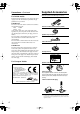
Supplied Accessories Precautions—Continued Make sure you have the following accessories: For British models Replacement and mounting of an AC plug on the power supply cord of this unit should be performed only by qualified service personnel.
Contents Important Safety Instructions .......................... 2 Precautions ....................................................... 3 Supplied Accessories ...................................... 4 Features ............................................................ 6 Multiroom Capability ........................................ 7 Getting to Know the AV Receiver ................... 8 Front Panel ..............................................................8 Display ......................................
Features Amplifier • • • • • 75 Watts/Channel @ 8 ohms (FTC) (TX-SR506) 80 Watts/Channel @ 8 ohms (FTC) (TX-SR576) 130 Watts/Channel @ 6 ohms (IEC) 160 Watts/Channel @ 6 ohms (JEITA) WRAT-Wide Range Amplifier Technology (5Hz–100kHz bandwidth) • High-Current Low-Impedance Drive (TX-SR506) • Optimum Gain Volume Circuitry • H.C.P.S. (High Current Power Supply) Massive High Power Transformer *1 Manufactured under license from Dolby Laboratories.
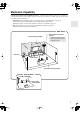
Multiroom Capability You can use two speaker systems with this AV receiver—a surround-sound speaker system (up to 7.1 channels) in your main listening room, a stereo speaker system in a second room, or Zone 2, as we call it. And, you can select a different audio source for each room. Main Room: In your main listening room, you can enjoy up to 7.1-channel playback (see page 14). You can enjoy the various listening modes such as Dolby and DTS (pages 55–60).
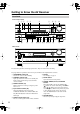
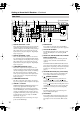
Getting to Know the AV Receiver Front Panel North American model 1 2 3 4 5 6 7 8 9 J MASTER VOLUME TUNING ON/STANDBY STANDBY PRESET ZONE 2 ENTER MUSIC OPTIMIZER MULTI CH DVD VCR/DVR CBL/SAT AUX TAPE TUNER CD SETUP RETURN AUX INPUT PHONES SETUP MIC ZONE 2 OFF TONE MOVIE/TV MUSIC GAME DISPLAY DIGITAL INPUT DIMMER VIDEO L AUDIO R MEMORY TUNING MODE CLEAR K L M N OP Q RS TUV W X Other models MASTER VOLUME TUNING ON/STANDBY STANDBY PRESET ZONE 2 ENTER PURE AUDI
Getting to Know the AV Receiver—Continued For detailed information, see the pages in parentheses. J MASTER VOLUME control (45) S DIGITAL INPUT button (42, 44) Sets the volume of the AV receiver to Min, 1 through 79, or Max. K PHONES jack (47) This 1/4-inch phone jack is for connecting a standard pair of stereo headphones for private listening. L MUSIC OPTIMIZER button (65) Turns the Music Optimizer on or off. M ZONE 2 and OFF buttons (79) The ZONE 2 button is used when setting Zone 2.
Getting to Know the AV Receiver—Continued Rear Panel 1 2 3 4 IN 3 HDMI 5 IN 2 6 IN 1 7 8 OUT SURR BACK SPEAKERS Bi-AMP for FRONT SPEAKERS ASSIGNABLE 9 Only some models SURR SPEAKERS FRONT SPEAKERS L DIGITAL IN L 120V COMPONENT VIDEO Y AM 1 (DVD) COAXIAL CB/ PB 2 VCR/DVR CBL/SAT DVD MONITOR OUT V (CBL/SAT) CENTER SPEAKER V R 1 IN 2 IN 1(DVD) OUT ASSIGNABLE 2 S S (VCR/DVR) (CD) IN IN OUT IN OUT IN IN IN OUT IN FRONT SURR R ANTENNA CR/ PR OPTICAL FM 7
Getting to Know the AV Receiver—Continued M CBL/SAT IN A cable or satellite receiver can be connected here. There are S-Video and composite video input jacks for connecting the video signal, and there are analog audio input jacks for connecting the audio signal. N VCR/DVR IN/OUT A video component, such as a VCR or DVR, can be connected here for recording and playback.
Remote Controller Controlling the AV Receiver C MULTI CH button (45) Selects the multichannel DVD input. To control the AV receiver, press the [RECEIVER] REMOTE MODE button to select Receiver mode. You can also use the remote controller to control your DVD player, CD player, and other components. See page 81 for more details. D Arrow [ ]/[ ]/[ ]/[ ] and ENTER buttons Used to select and adjust settings. E SETUP button Used to change settings.
Remote Controller—Continued Installing the Batteries 1 To open the battery compartment, press the small lever and remove the cover. Using the Remote Controller When using the remote controller, point it toward the AV receiver’s remote control sensor, as shown below. Remote control sensor STANDBY indicator AV receiver 30˚ 2 3 Insert the two supplied batteries (AA/R6) in accordance with the polarity diagram inside the battery compartment. Replace the cover and push it shut.
Connecting Your Speakers Enjoying Home Theater Thanks to the AV receiver’s superb capabilities, you can enjoy surround sound with a real sense of movement in your own home—just like being in a movie theater or concert hall. You can enjoy DVDs featuring Dolby Digital or DTS. With analog or digital TV, you can enjoy Dolby Pro Logic IIx, DTS Neo:6, or Onkyo’s original DSP listening modes. Front left and right speakers These output the main sound.
Connecting Your Speakers—Continued Speaker Configuration Connecting a Powered Subwoofer For 7.1-channel surround-sound playback, you need seven speakers and a powered subwoofer. Using a suitable cable, connect the AV receiver’s PRE OUT: SUBWOOFER to the input on your powered subwoofer. If your subwoofer is unpowered and you’re using an external amplifier, connect the PRE OUT: SUBWOOFER to the amp’s input. The following table shows which channels you should use based on the number of speakers you have.
Connecting Your Speakers—Continued Speaker Connection Precautions Read the following before connecting your speakers: • North American models: You can connect speakers with an impedance of between 6 and 16 ohms. If you use speakers with a lower impedance, and use the amplifier at high volume levels for a long period of time, the built-in amp protection circuit may be activated. • Other models: You can connect speakers with an impedance of between 4 and 16 ohms.
Connecting Your Speakers—Continued Bi-amping Speaker Hookup Bi-amping Front Speakers The FRONT L/R and SURR BACK L/R terminal posts can be used with front speakers and surround back speakers respectively, or bi-amped to provide separate tweeter and woofer feeds for front speakers, providing improved bass and treble performance. • When bi-amping is used, the AV receiver is able to drive up to 5.1 speakers in the main room.
Connecting Antennas This section explains how to connect the supplied indoor FM antenna and AM loop antenna, and how to connect commercially available outdoor FM and AM antennas. The AV receiver won’t pick up any radio signals without any antenna connected, so you must connect the antenna to use the tuner. AM antenna push terminals Connecting the AM Loop Antenna The supplied indoor AM loop antenna is for indoor use only. 1 Assemble the AM loop antenna, inserting the tabs into the base, as shown.
Connecting Antennas—Continued Connecting an Outdoor FM Antenna Connecting an Outdoor AM Antenna If you cannot achieve good reception with the supplied indoor FM antenna, try a commercially available outdoor FM antenna instead. If good reception cannot be achieved using the supplied AM loop antenna, an outdoor AM antenna can be used in addition to the loop antenna, as shown.
Connecting Your Components AV Connection Color Coding About AV Connections RCA-type AV connections are usually color coded: red, white, and yellow. Use red plugs to connect rightchannel audio inputs and outputs (typically labeled “R”). Use white plugs to connect left-channel audio inputs and outputs (typically labeled “L”). And use yellow plugs to connect composite video inputs and outputs. • Before making any AV connections, read the manuals supplied with your other AV components.
Connecting Your Components—Continued Connecting Audio and Video Signals to the AV Receiver By connecting both the audio and video outputs of your DVD player and other AV components to the AV receiver, you can switch the audio and video signals simultaneously simply by changing the input source on the AV receiver. : Signal Flow Video Video Audio Audio TV, projector, etc. DVD player, etc.
Connecting Your Components—Continued Connecting a TV or Projector Step 1: Video Connection Choose a video connection that matches your TV ( A , B , or C ), and then make the connection. Step 2: Audio Connection Choose an audio connection that matches your TV ( a , b , or c ), and then make the connection. • With connection a , you can listen to and record audio from your TV or listen in Zone 2. • To enjoy Dolby Digital and DTS, use connection b or c .
Connecting Your Components—Continued Connecting a DVD player Step 1: Video Connection Choose a video connection that matches your DVD player ( A , B , or C ), and then make the connection. You must connect the AV receiver to your TV with the same type of connection. Step 2: Audio Connection Choose an audio connection that matches your DVD player ( a , b , or c ), and then make the connection. • With connection a , you can listen to and record audio from a DVD or listen in Zone 2.
Connecting Your Components—Continued Hooking Up the Multichannel Input If your DVD player supports multichannel audio formats such as DVD-Audio and SACD, and it has a multichannel analog audio output, you can connect it to the AV receiver’s multichannel input. Use a multichannel analog audio cable, or several normal audio cables, to connect the AV receiver’s DVD IN FRONT L/R, CENTER, SURR L/R, SURR BACK L/R, and SUBWOOFER jacks to the 7.1-channel analog audio output on your DVD player.
Connecting Your Components—Continued Connecting a VCR or DVR for Playback With this hookup, you can use the tuner in your VCR or DVR to listen to your favorite TV programs via the AV receiver, which is useful if your TV has no audio outputs. Hint! Step 1: Video Connection Choose a video connection that matches your VCR or DVR ( A , B , or C ), and then make the connection. You must connect the AV receiver to your TV with the same type of connection.
Connecting Your Components—Continued Connecting a VCR or DVR for Recording Step 1: Video Connection Choose a video connection that matches your VCR or DVR ( A or B ), and then make the connection. The video source to be recorded must be connected to the AV receiver via the same type of connection. Step 2: Audio Connection Make the audio connection a .
Connecting Your Components—Continued Connecting a Satellite, Cable, or Terrestrial Set-top box or Other Video Source With this hookup, you can use your satellite or cable receiver to listen to your favorite TV programs via the AV receiver, which is useful if your TV has no audio outputs. Hint! Step 1: Video Connection Choose a video connection that matches the video source ( A , B , or C ), and then make the connection. You must connect the AV receiver to your TV with the same type of connection.
Connecting Your Components—Continued Connecting Components with HDMI About HDMI Designed to meet the increased demands of digital TV, HDMI (High Definition Multimedia Interface) is a new digital interface standard for connecting TVs, projectors, DVD players, set-top boxes, and other video components. Until now, several separate video and audio cables have been required to connect AV components.
Connecting Your Components—Continued ■ Audio Signals For TX-SR506 • Audio and video signals received via inputs other than the HDMI IN jacks are not output by the HDMI OUT. • Audio and video signals received via the HDMI IN jacks are output only by the HDMI OUT. • To watch an HDMI source that’s connected via the AV receiver’s HDMI jacks, the AV receiver must be turned on, otherwise no HDMI signal will be output.
Connecting Your Components—Continued Connecting a Camcorder, Game Console, or Other Device Step 1: Make the video connection A . Step 2: Make the audio connection a . a MASTER VOLUME TUNING PRESET AUX INPUT L AUDIO R ENTER SETUP L AUDIO R OUT RETURN AUX INPUT SETUP MIC VIDEO L AUDIO R A AUX INPUT VIDEO VIDEO OUT Camcorder, game console, etc.
Connecting Your Components—Continued Connecting a CD Player or Turntable ■ CD Player or Turntable (MM) with Built-in Phono Preamp Step 1: Choose a connection that matches your CD player ( a , b , or c ). Use connection a for a turntable with a built-in phono preamp.
Connecting Your Components—Continued Connecting a Cassette, CDR, MiniDisc, or DAT Recorder Step 1: Choose a connection that matches your recorder ( a , b , or c ), and then make the connection.
Connecting Your Components—Continued Connecting an RI Dock ■ If Your iPod Doesn’t Support Video: Connect your RI Dock’s audio output jacks to the AV receiver’s TAPE IN L/R jacks. Not all iPod models output video. For information about which iPod models are supported by the RI Dock, see the RI Dock’s instruction manual.
Connecting Your Components—Continued Connecting Onkyo Components Step 1: Make sure that each Onkyo component is connected to the AV receiver with an analog audio cable (RCA). Step 2: Make the necessary connections (see illustration below). Step 3: If you’re using an MD, CDR, or RI DOCK component, change the Input Display (see page 43).
Turning On the AV Receiver ON/STANDBY ON/STANDBY STANDBY indicator MASTER VOLUME TUNING STANDBY/ON STANDBY RECEIVER PRESET ZONE 2 ENTER PURE AUDIO PURE AUDIO DVD MULTI CH VCR/DVR CBL/SAT AUX TAPE TUNER CD SETUP RETURN AUX INPUT PHONES SETUP MIC ZONE 2 OFF TONE MOVIE/TV MUSIC GAME DISPLAY DIGITAL INPUT VIDEO L AUDIO R RT/PTY/TP MEMORY TUNING MODE CLEAR Turning On and Standby Remote controller AV receiver ON/STANDBY or On the AV receiver, press the [ON/STANDBY] button.
First Time Setup This section explains the settings that you need to make before using the AV receiver for the very first time. Using Audyssey 2EQ Automatic Speaker Setup (Audyssey 2EQ) With the supplied calibrated microphone, Audyssey 2EQ automatically determines the number of speakers connected, their size for purposes of bass management, optimum crossover frequencies to the subwoofer (if present), and distances from the primary listening position.
First Time Setup—Continued • Do not attempt to hold the microphone in your hand during measurements as this will produce incorrect results. 3 Press [ENTER]. The automatic speaker setup starts. You can cancel the automatic speaker setup at any point in this procedure simply by disconnecting the setup microphone. 6 When the automatic speaker setup is complete, disconnect the speaker setup microphone.
First Time Setup—Continued For TX-SR506 To Retry the Automatic Speaker Setup Press the [ENTER] button. Make sure speakers that cannot be detected are connected properly. 1 Press the [RECEIVER] button, followed by the [SETUP] button. 2 Use the Up and Down [ ]/[ ] buttons to select “0.HardwareSetup,” and then press [ENTER]. 3 Use use the Left and Right [ ]/[ ] buttons to select the speaker impedance: 4 ohms: Select if the impedance of any speaker is 4 ohms or more but less than 6.
First Time Setup—Continued For TX-SR576 1 6 Press the [RECEIVER] button, followed by the [SETUP] button. Press the [SETUP] button. Setup closes. Note: • This procedure can also be performed on the AV receiver by using its [SETUP], [ENTER], and arrow buttons. 2 Use the Up and Down [ ]/[ ] buttons to select “2. Speaker Setup,” and then press [ENTER]. HDMI Input Setup If you connect a video component to an HDMI IN, you must assign that input to an input selector.
First Time Setup—Continued 4 Press the [SETUP] button. Setup closes. 4 Use the Up and Down [ ]/[ ] buttons to select an input selector, and use the Left and Right [ ]/[ ] buttons to select: HDMI1: Select if the video component is connected to HDMI IN 1. HDMI2: Select if the video component is connected to HDMI IN 2. HDMI3: Select if the video component is connected to HDMI IN 3. - - - - -: Select if you’re not using the HDMI OUT. 5 Press the [SETUP] button. Setup closes.
First Time Setup—Continued Component Video Input Setup If you connect a video component to a COMPONENT VIDEO IN, you must assign that input to an input selector. For example, if you connect your DVD player to COMPONENT VIDEO IN 2, you must assign COMPONENT VIDEO IN 2 to the DVD input selector. By default, the DVD input selector is assigned to COMPONENT VIDEO IN 1, and all of the other input selectors (i.e., VCR/DVR, CBL/SAT, AUX) are assigned to the “- - -” option.
First Time Setup—Continued Digital Input Setup OPT2: Select if the component is connected to DIGITAL IN OPTICAL 2. - - -: Select if the component is connected to an analog input.
First Time Setup—Continued 3 Use the Up and Down [ ]/[ ] buttons to select “1-3.Digital,” and then press [ENTER]. Changing the Input Display If you connect an -capable Onkyo MiniDisc recorder, CD recorder, or RI Dock to the TAPE IN/OUT jacks, or connect an RI Dock to the CBL/SAT jacks, for to work properly, you must change this setting. This setting can only be changed on the AV receiver.
First Time Setup—Continued Automatic Audio Input Selection Setup (TX-SR576 only) 3 DIGITAL INPUT MASTER VOLUME TUNING STANDBY/ON STANDBY PRESET ZONE 2 ENTER PURE AUDIO PURE AUDIO DVD MULTI CH VCR/DVR CBL/SAT AUX TAPE TUNER CD SETUP RETURN AUX INPUT PHONES SETUP MIC ZONE 2 OFF TONE MOVIE/TV MUSIC GAME DISPLAY DIGITAL INPUT VIDEO L AUDIO R RT/PTY/TP MEMORY TUNING MODE CLEAR 1 2, 3 When an input source is selected, the AV receiver checks the relevant audio inputs for the p
Playing Your AV Components Basic AV Receiver Operation 3 MASTER VOLUME TUNING STANDBY/ON STANDBY 1 3 PRESET ZONE 2 ENTER PURE AUDIO PURE AUDIO DVD MULTI CH VCR/DVR CBL/SAT AUX TAPE TUNER CD SETUP RETURN AUX INPUT PHONES SETUP MIC ZONE 2 OFF TONE MOVIE/TV MUSIC GAME DISPLAY DIGITAL INPUT VIDEO L AUDIO R RT/PTY/TP MEMORY TUNING MODE CLEAR 1 1 Use the AV receiver’s input selector buttons to select an input source.
Common Functions This section explains functions that can be used with any input source. Muting the AV Receiver You can temporarily mute the output of the AV receiver. DISPLAY Press [RECEIVER] first MUTING Press the [RECEIVER] REMOTE MODE button, and then press the remote controller’s [MUTING] button. The output is muted and the MUTING indicator flashes on the display. To unmute the AV receiver, press the remote controller’s [MUTING] button again, or adjust the volume.
Common Functions—Continued 7Using Headphones Displaying Source Information For private listening, you can connect a pair of stereo headphones (1/4-inch phone plug) to the AV receiver’s PHONES jack. Press the [RECEIVER] REMOTE MODE button, and then press the [DISPLAY] button repeatedly to cycle through the available information. STANDBY/ON STANDBY ZONE 2 PURE AUDIO PURE AUDIO You can display various information about the current input source as follows.
Common Functions—Continued Specifying the Digital Signal Format The following table shows the display indicator for each digital signal format. Format Display Dolby Digital DTS PCM PCM Normally, the AV receiver detects the format of digital input signals automatically. However, if you experience either of the following issues when playing PCM or DTS sources, you can specify the signal format manually. • If the beginnings of tracks from a PCM source are cut off, try the PCM setting.
Listening to the Radio AM Frequency Step Setup (on some models) 2 Use the Up and Down [ ]/[ ] buttons to select “0.HardwareSetup,” and then press [ENTER]. 3 Use the Up and Down [ ]/[ ] buttons to select “AM Freq.” 4 Use the Left and Right [ ]/[ ] buttons to select: 10kHz: Select if 10kHz steps are used in your area. 9kHz: Select if 9kHz steps are used in your area. 5 Press the [SETUP] button. Setup closes.
Listening to the Radio—Continued ■ Manual Tuning Mode Listening to AM/FM Stations 1 TUNING TUNER TUNING MODE Press the [TUNING MODE] button so that the AUTO indicator disappears from the display.
Listening to the Radio—Continued ■ Tuning into Stations by Frequency You can tune into AM and FM stations directly by entering the appropriate frequency.
Listening to the Radio—Continued Selecting Presets Presetting AM/FM Stations PRESET 2, 4 3 MASTER VOLUME TUNING STANDBY/ON STANDBY MASTER VOLUME PRESET ZONE 2 ENTER PURE AUDIO TUNING STANDBY/ON STANDBY PRESET ZONE 2 PURE AUDIO ENTER DVD MULTI CH VCR/DVR CBL/SAT AUX TAPE TUNER CD SETUP RETURN PURE AUDIO AUX INPUT PHONES SETUP MIC ZONE 2 OFF TONE MOVIE/TV MUSIC GAME DISPLAY DIGITAL INPUT VIDEO L AUDIO R RT/PTY/TP MEMORY TUNING MODE CLEAR PURE AUDIO DVD MULTI CH
Listening to the Radio—Continued Using RDS (European models only) RDS only works in areas where RDS broadcasts are available. When tuned to an RDS station, the RDS indicator appears. RDS indicator ■ What is RDS? RDS stands for Radio Data System and is a method of transmitting data in FM radio signals. It was developed by the European Broadcasting Union (EBU) and is available in most European countries. RDS is approved by the National Radio Systems Committee (NRSC) and is available in North America.
Listening to the Radio—Continued Displaying Radio Text (RT) 4 RT/PTY/TP To start the search, press [ENTER]. The AV receiver searches until it finds a station of the type you specified, at which point it stops briefly before continuing with the search.
Using the Listening Modes Selecting with the Remote Controller Selecting the Listening Modes For a description of each listening mode, see “About the Listening Modes” on page 59. • The Dolby Digital and DTS listening modes can only be selected if your DVD player is connected to the AV receiver with a digital audio connection (coaxial, optical, or HDMI). MOVIE/TV MUSIC STEREO GAME • The listening modes you can select depends on the format of the input signal.
Using the Listening Modes—Continued Listening Modes Available for Each Source Format Analog and PCM Sources PCM Source format Media Button [PURE AUDIO] Listening Mode Multichannel 32–96 176.
Using the Listening Modes—Continued Dolby Digital and Dolby Digital Plus Sources Multichannel Media Button [PURE AUDIO] Dolby Digital Plus*1 Mono/Multiplex Multichannel 2ch Mono/Multiplex Dolby Digital Source format 2ch DVD, DTV, etc.
Using the Listening Modes—Continued DTS Sources DTS, DTS 96/24 Source format Multichannel Media Button Mono DTS, DTS 96/24 Mono DVD, CD, etc. Listening Mode [PURE AUDIO] Pure Audio*1 2ch ✔ ✔ ✔ ✔ ✔ DVD, CD, etc.
Using the Listening Modes—Continued About the Listening Modes The AV receiver’s listening modes can transform your listening room into a movie theater or concert hall, with high fidelity and stunning surround sound. The illustration shows which speakers are active in each listening mode with 7.1 channel speaker system. Front left Center Front right • Dolby PLIIx Game Use this mode with video games, especially those that bear the Dolby Pro Logic II logo.
Using the Listening Modes—Continued DTS-ES Discrete Onkyo Original DSP Modes This mode is for use with DTS-ES Discrete soundtracks, that use a discrete surround back channel for true 6.1/7.1-channel playback. The seven totally separate audio channels provide better spatial imaging and 360degree sound localization, perfect for sounds that pan across the surround channels. Use it with DVDs that bear the DTS-ES logo, especially those with a DTS-ES Discrete soundtrack.
Recording This section explains how to record the input source and how to record audio and video from separate sources. Notes: • The surround sound and DSP listening modes cannot be recorded. • Copy-protected DVDs cannot be recorded. • Sources connected to the analog multichannel input cannot be recorded. • Sources connected to a digital input cannot be recorded. Only analog inputs can be recorded. • DTS signals will be recorded as noise, so don’t attempt analog recording of DTS CDs or LDs.
Adjusting the Listening Modes Using the Audio Adjust Settings With the Audio Adjust functions and settings, you can adjust the sound and listening modes as you like. For TX-SR506 1 62 For TX-SR576 1 Press the [RECEIVER] REMOTE MODE button, followed by the [SETUP] button. 2 Use the Up and Down [ ]/[ ] buttons to select “3. Audio Adjust,” and then press [ENTER]. 3 Use the Up and Down [ ]/[ ] buttons to select an item, and then press [ENTER].
Adjusting the Listening Modes—Continued The Audio Adjust settings are explained below. Multiplex/Mono Settings Multiplex ■ Input (Mux) This setting determines which channel of a stereo multiplex source is output. Use it to select audio channels or languages with multiplex sources, multilingual TV broadcasts, and so on. Main: The main channel is output (default). Sub: The sub channel is output. M/S: Both the main and sub channels are output.
Adjusting the Listening Modes—Continued T–D (Theater-Dimensional) Setting 2 Use the Up and Down [ ]/[ ] buttons to select an item. 3 Use the Left and Right [ ]/[ ] buttons to change the setting. Repeat this step for the other settings. ■ LstnAngl (Listening Angle) With this setting, you can optimize the Theater-Dimensional listening mode by specifying the angle of the front left and right speakers relative to the listening position.
Adjusting the Listening Modes—Continued • The effect of the Late Night function depends on the material that you are playing and the intention of the original sound designer, and with some material there will be little or no effect when you select the different options. • The Late Night function is set to Off when the AV receiver is set to Standby. CinemaFILTER ■ Cinema Fltr With the CinemaFILTER, you can soften overly bright movie soundtracks, which are typically mixed for reproduction in a movie theater.
Adjusting the Listening Modes—Continued Listening Mode Presets (TX-SR576 only) 4 On the Listening Mode Preset menu, you can specify a default listening mode for each of the audio formats supported by each input selector. The AV receiver will then select the listening mode automatically depending on the format of the input signal. You can still select the other listening modes, although the default listening mode will be used the next time you turn on the AV receiver.
Advanced Setup Speaker Setup 4 While the “Subwoofer” setting is selected, use the Left and Right [ ]/[ ] buttons to select Yes or No. Yes: Select if a subwoofer is connected. No: Select if no subwoofer is connected. 5 Use the Down [ ] button to select “Front,” and then use the Left and Right [ ]/[ ] buttons to select Small or Large. Small: Select if the front speakers are small. Large: Select if the front speakers are large.
Advanced Setup—Continued 8 9 Use the Down [ ] button to select “SurrBack (SurrB),” and use the Left and Right [ ]/[ ] buttons to select Small, Large, or None. Small: Select if the surround back speakers are small. Large: Select if the surround back speakers are large. None: Select if no surround back speakers are connected. Notes: • If the Surround setting in step 7 is set to None, or Powered Zone 2 is being used, this setting does not appear.
Advanced Setup—Continued Double Bass 2 Press the [RECEIVER] REMOTE MODE button, followed by the [SETUP] button. If you have a TX-SR506, proceed to step 4. 3 (TX-SR576 only) Use the Up and Down [ ]/[ ] buttons to select “2.Speaker Setup,” and then press the [ENTER] button. 4 Use the Up and Down [ ]/[ ] buttons to select “Sp Distance,” and then press [ENTER]. 5 While “Unit” is displayed, use the Left and Right [ ]/[ ] buttons to select “feet” or “meters”. feet: Distances can be set in feet.
Advanced Setup—Continued 8 Press the [SETUP] button. Setup closes. Notes: • The Center and Subwoofer distances can be set up to 5 ft. (1.5 m) more or less than the Left distance. For example, if the Left distance is set to 20 ft. (6 m), the Center and Subwoofer distances can be set between 15 and 25 ft. (4.5 and 7.5 m). • The Surround and Surround Back distances can be set up to 5 ft. (1.5 m) more or 15 ft. (4.5 m) less than the Left distance. For example, if the Left distance is set to 20 ft.
Advanced Setup—Continued Equalizer Settings 5 Press the Down [ ] button, and then use the Left and Right [ ]/[ ] buttons to select a speaker. 6 Use the Up and Down [ ]/[ ] buttons to select a frequency. Use the Left and Right [ ]/[ ] buttons to adjust the level at that frequency. These settings are set automatically by the Automatic Speaker Setup function (see page 36). Here you can adjust the tone of individual speakers. To set the volume of individual speakers, see page 70.
Advanced Setup—Continued • This procedure can also be performed on the AV receiver by using its [SETUP], [ENTER], and arrow buttons. 5 Use the Left and Right [ ]/[ ] buttons to change it. The Source Setup menu items are explained below. 6 When you’ve finished, press the [SETUP] button. Setup closes. Source Setup (TX-SR576 only) This section explains items on the Source Setup menu. Items can be set individually for each input selector.
Advanced Setup—Continued Miscellaneous Setup (TX-SR576 only) This section explains items on the Miscellaneous menu. 1 Press the [RECEIVER] REMOTE MODE button, followed by the [SETUP] button. Volume Setup ■ MaxVolume With this setting, you can limit the maximum volume. The Maximum Volume range is Off, 79 to 30. ■ PowOn Vol This setting determines what the volume will be each time the AV receiver is turned on. The range is Last, Min, 1 to 79, Max.
Advanced Setup—Continued Hardware Setup (TX-SR576 only) 4 Use the Up and Down [ ]/[ ] buttons to select an item, and use the Left and Right [ ]/[ ] buttons to change it. The items are explained below. 5 When you’ve finished, press the [SETUP] button. Setup closes. This section explains items on the Hardware menu. Remote indicator RECEIVER Note: • This procedure can also be performed on the AV receiver by using its [SETUP], [ENTER], and arrow buttons.
Advanced Setup—Continued Tuner ■ AM Freq (on some models) See “AM Frequency Step Setup (on some models)” on page 49. AnalogMulti ■ SW In Sens Some DVD players output the LFE channel from their analog subwoofer output at 15 dB higher than normal. With this setting, you can change the AV receiver’s subwoofer sensitivity to match your DVD player. Note that this setting only affects signals connected to the AV receiver’s MULTI CH SUBWOOFER jack. You can select 0 dB, 5 dB, 10 dB, or 15 dB.
Advanced Setup—Continued PowCtrl To link the power functions of RIHD-compatible components connected via HDMI, select Enable. Disable: Power Control disabled. Enable: Power Control enabled. Notes: • The Power Control setting can be set only when the above Control setting is set to Enable. • HDMI power control only works with RIHD-compatible components that support it and may not work properly with some components due to their settings or compatibility.
Zone 2 In addition to your main listening room, you can also enjoy playback in the other room, or as we call Zone 2. And, you can select a different source for each room. Connecting Your Zone 2 Speakers to an Amp in Zone 2 Connecting Zone 2 There are two ways you can connect Zone 2 speakers: 1. Connect them directly to the AV receiver. 2. Connect them to an amp in Zone 2. Connecting Your Zone 2 Speakers Directly to the AV receiver This setup allows 5.
Zone 2—Continued Powered Zone 2 Setting 3 (TX-SR576 only) Use the Up and Down [ ]/[ ] buttons to select “7-2.Zone2,” and then press [ENTER]. 4 Use the Up and Down [ ]/[ ] buttons to select “PwrdZ2.”. 5 Use the Left and Right [ ]/[ ] buttons to select: Not Act: ZONE 2 SPEAKERS L/R speaker terminals not activated (Powered Zone 2 disabled). Act: ZONE 2 SPEAKERS L/R speaker terminals activated (Powered Zone 2 enabled). 6 Press the [SETUP] button. Setup closes.
Zone 2—Continued Using Zone 2 This section explains how to turn Zone 2 on and off, how to select an input source for Zone 2, and how to adjust the volume for Zone 2. • While Powered Zone 2 is being used, listening modes that require surround back speakers (6.1/7.1), such as Dolby Digital EX and DTS-ES are unavailable.
Zone 2—Continued Adjusting the Volume of Zones Remote controller On the remote controller, press the [ZONE 2] REMOTE MODE button, and then use the VOL [ ]/[ ] button. Muting Zones On the remote controller, press the [ZONE 2] REMOTE MODE button, and then press the [MUTING] button. To unmute a zone, on the remote controller, press the [ZONE 2] REMOTE MODE button, and then press the [MUTING] button again.
Controlling Other Components You can control your DVD player, CD player, and other components with the AV receiver’s remote controller. To control another component, you must first enter that component’s remote control code to a REMOTE MODE button. This section explains how to enter remote control codes and how to control your other components. 1 Look up the component’s remote control code in the separate Remote Control Codes list. The codes are organized by category.
Controlling Other Components—Continued Remote Control Codes for Onkyo Components Connected via Resetting the REMOTE MODE Buttons Onkyo components that are connected via are controlled by pointing the remote controller at the AV receiver, not the component. This allows you to control components that are out of view, in a rack, for example. 1 Make sure the Onkyo component is connected with an cable and an analog audio cable (RCA). See page 34 for details.
Controlling Other Components—Continued Controlling a DVD Player, or DVD Recorder By pressing the REMOTE MODE button that’s been programmed with the remote control code for your DVD player (HD DVD, Blu-ray, or TV/DVD combination), you can control your player with the following buttons. A ON/STANDBY button The [DVD] REMOTE MODE button is preprogrammed with the remote control code for controlling an Onkyo DVD player.
Controlling Other Components—Continued T PLAY MODE button Selects play modes on components with selectable play modes. U CLR button Cancels functions and clears entered numbers. Note: • If you enter the remote control code for a HD DVD or Blu-ray player that has A, B, C, and D buttons, the [SEARCH], [REPEAT], [RANDOM], and [PLAY MODE] buttons will work as the A (red), B (green), C (blue), and D (yellow) buttons respectively.
Controlling Other Components—Continued Controlling a Satellite Receiver or Cable Receiver By pressing the REMOTE MODE button that’s been programmed with the remote control code for your satellite receiver, cable receiver, or DVD recorder (DBS/PVR combination or cable/PVR combination), you can control your player with the following buttons. For details on entering a remote control code for a different component, see page 81. A ON/STANDBY button Set the component to On or Standby.
Controlling Other Components—Continued Controlling a CD Player, CD Recorder, or MD Player By pressing the REMOTE MODE button that’s been programmed with the remote control code for your CD player, CD recorder, or MD player, you can control your player with the following buttons. A ON/STANDBY button The [CD] REMOTE MODE button is preprogrammed with the remote control code for controlling an Onkyo CD player.
Controlling Other Components—Continued Controlling an RI Dock By pressing the REMOTE MODE button that’s been programmed with the remote control code for your RI Dock, you can control your iPod in the RI Dock with the following buttons. The [DOCK] REMOTE MODE button is preprogrammed with the remote control code for controlling an RI Dock when used with an connection. For details on entering a remote control code, see page 81.
Controlling Other Components—Continued P Fast Forward [ Works as a Resume button when used with a DS-A2 RI Dock. ] button Press and hold to fast forward. S RANDOM button* Q Stop [ ] button Used with the shuffle function. Stops playback and displays a menu. R PLAY MODE button Selects play modes on components with selectable play modes. *Buttons marked with an asterisk (*) are not supported by 3rd generation iPod models.
Controlling Other Components—Continued Controlling a TV By pressing the [TV] REMOTE MODE button that’s been programmed with the remote control code for your TV (TV/DVD combination or TV/VCR combination), you can control your TV with the following buttons. A ON/STANDBY, TV [ For details on entering a remote control code for a different component, see page 81.
Troubleshooting If you have any trouble using the AV receiver, look for a solution in this section. If you can’t resolve the issue yourself, contact your Onkyo dealer. If you can’t resolve the issue yourself, try resetting the AV receiver before contacting your Onkyo dealer. To reset the AV receiver to its factory defaults, turn it on and, while holding down the [VCR/DVR] button, press the [ON/STANDBY] button. “Clear” will appear on the display and the AV receiver will enter Standby mode.
Troubleshooting—Continued The surround back speakers produce no sound • The surround back speakers are not used with all listening modes. Try another listening mode (page 55). • Not much sound may be produced by the surround back speakers with some sources. • Check the Speaker Configuration (page 67). • While Powered Zone 2 is being used, playback in the main room is reduced to 5.1-channels and the surround back speakers produce no sound (page 77).
Troubleshooting—Continued There’s no picture from a source connected to an HDMI IN • Reliable operation with an HDMI-to-DVI adapter is not guaranteed. In addition, video signals from a PC are not supported (page 28). • If the message “Resolution Error” appears on the AV receiver’s display, this indicates that your TV does not support the current video resolution and you need to select another resolution on your DVD player.
Troubleshooting—Continued The following settings can be made for the S-Video and composite video inputs You must use the buttons on the unit to make these settings. 1. While holding down the input selector button for the input source that you want to set, press the [SETUP] button. 2. Use the Left and Right [ ]/[ ] buttons to change the setting. 3. Press the [SETUP] button when you’ve finished. • Video Attenuation This setting can be made for the DVD, VCR/DVR, CBL/SAT, or AUX input.
Specifications TX-SR506 Amplifier Section General Rated Output Power North American: 75 watts minimum continuous power per channel, 8 ohm loads, 2 channels driven from 20Hz to 20kHz, with a maximum total harmonic distortion of 0.08% (FTC) 100 watts minimum continuous power per channel, 6 ohm loads, 2 channels driven at 1kHz, with a maximum total harmonic distortion of 0.
Specifications—Continued TX-SR576 Amplifier Section General Rated Output Power North American: 80 watts minimum continuous power per channel, 8 ohm loads, 2 channels driven from 20Hz to 20kHz, with a maximum total harmonic distortion of 0.08% (FTC) 90 watts minimum continuous power per channel, 8 ohm loads, 2 channels driven at 1kHz, with a maximum total harmonic distortion of 0.
Memo Sales & Product Planning Div. : 2-1, Nisshin-cho, Neyagawa-shi, OSAKA 572-8540, JAPAN Tel: 072-831-8023 Fax: 072-831-8163 ONKYO U.S.A. CORPORATION 18 Park Way, Upper Saddle River, N.J. 07458, U.S.A. Tel: 201-785-2600 Fax: 201-785-2650 http://www.us.onkyo.com/ ONKYO EUROPE ELECTRONICS GmbH Liegnitzerstrasse 6, 82194 Groebenzell, GERMANY Tel: +49-8142-4401-0 Fax: +49-8142-4401-555 http://www.eu.onkyo.