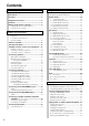
Contents Before using AV Receiver TX-DS989 Instruction Manual Important Safeguards ....................................... 2 Precautions ........................................................ 3 Contents ............................................................ 4 Supplied accessories ......................................... 5 Features ............................................................. 6 Before using remote controller .........................
WARNING: TO REDUCE THE RISK OF FIRE OR ELECTRIC SHOCK, DO NOT EXPOSE THIS APPLIANCE TO RAIN OR MOISTURE. CAUTION: TO REDUCE THE RISK OF ELECTRIC SHOCK, DO NOT REMOVE COVER (OR BACK). NO USER-SERVICEABLE PARTS INSIDE. REFER SERVICING TO QUALIFIED SERVICE PERSONNEL.
21. Replacement Parts–When replacement parts are required, be sure the service technician has used replacement parts specified by the manufacturer or have the same characteristics as the original part. Unauthorized substitutions may result in fire, electric shock, or other hazards. 22. Safety Check – Upon completion of any service or repairs to the appliance, ask the service technician to perform safety checks to determine that the appliance is in proper operation condition. 23.
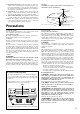
Contents Before using Setting OSD menu Important Safeguards ......................................... 2 The On-Screen Display (OSD) menu .............. 28 Precautions ......................................................... 3 Navigating through the OSD menu ................................ 29 Contents .............................................................. 4 Speaker Setup ................................................... 30 Supplied accessories .........................................
Contents Recording a source .......................................... 54 Using a Macro function .................................... 64 To record the input source signal you are currently watching or listening to .......................................... 54 To record an input source signal different from that you are currently watching or listening to ............. 55 Recording the video from one source and the audio from another ............................................
Features ■ AMPLIFIER FEATURES ■ AUDIO/VIDEO FEATURES 130 WATTS MINIMUM OF CONTINUOUS RMS POWER to each of the 7channels into 8 Ω, from 20 Hz to 20 kHz with no more than 0.05%THD (FTC rating)–clean high-current amplification provides incredible dynamic range for seamless reproduction of even the most demanding cinema soundtracks, as well as animatedly rich music at any volume level.
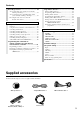
Before using remote controller Installing the remote controller batteries 1. Remove the battery compartment cover by pressing the tab and sliding the cover. 2. Insert two AA (R6 or UM-3) batteries into the battery compartment. Carefully follow the polarity diagram (positive (+) and negative (–) symbols) inside the battery compartment. 1 3. After batteries are installed and seated correctly, replace the compartment cover.
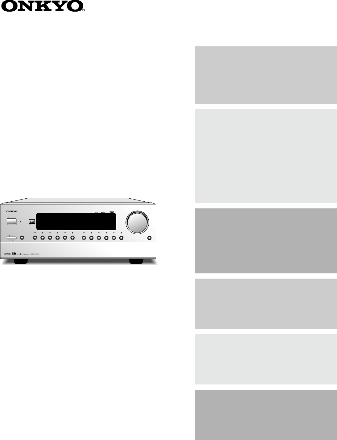
Front panel facilities Here is an explanation of the controls and displays on the front panel of the TX-DS989.
Front panel facilities Front panel Digital format: The current input source is set for a digital format of “Auto.” POWER After plugging in the power cord into the rear panel and wall outlet, pressing this button connects the TX-DS989 to the AC mains and turns it on. • Before turning on the power, make sure all cables are properly connected. • Turning on the TX-DS989 may cause a momentary power surge that might interfere with other electrical equipment on the same circuit.
Front panel facilities Off When not using either Rec Out or Zone 2, press that button and then press the Off button to turn off the signal. If the Rec Out or Zone 2 signal is turned on and the connected component is not turned on, the electric signal will still be sent through the circuitry and the excess load may cause deterioration of the audio signal. DSP Press these buttons to scroll through the listening modes and set a new one for the input source you are currently listening to.
Remote controller SEND/LEARN indicator 1 LCD display POWER ON/STNBY button Be aware that pressing the STNBY button only places the TX-DS989 in standby and does not turn the power completely off.
Rear panel facilities • Be sure to always refer to the instructions that came with the component that you are connecting. • Do not plug in the power cord until all connections have been made. • For input jacks, red connectors (marked R) are used for the right channel, white connectors (marked L) are used for the left channel, and yellow connectors (marked V) are used for video connection. • Insert all plugs and connectors securely.
Rear panel facilities ANTENNA These jacks are for connecting the FM indoor antenna and AM loop antenna that are supplied with the TX-DS989. AMP IN These jacks are for connecting a graphic equalizer for further control of the audio output. • When connecting a graphic equalizer, remove the attached jumper plugs and store them carefully so as not to lose them. • Only remove the jumper plugs when required. After you finish using an AMP IN jack, replace the jumper plug.
Rear panel facilities AC INLET Plug the supplied power cord into this AC INLET and then into the power outlet on the wall. Power cord (supplied) Front left (Blue) Front right (Red) Center (Green) Surround left (Black) Surround right (Yellow) Subwoofer (Brown) To an AC wall outlet • Do not use a power cord other than the one supplied with the TX-DS989. The power cord supplied is designed for use with the TX-DS989 and should not be used with any other device.
Rear panel facilities z connector VIDEO IN/OUT These are the video inputs and outputs. There are 6 video inputs and 2 video outputs and each one includes both composite video and S-video configurations. Connect VCRs, LD players, DVD players, and other video components to the video inputs. S-video sources can be viewed via the S-video or composite outputs, while composite sources can only be viewed through the composite output.
Example of how to connect your equipment VCR (VIDEO 1) 7. Refer to page 19 R TV monitor (MONITOR OUT 1) 10. Refer to page 19 L Cable/Satellite (Set top box, VIDEO 3) 8. Refer to page 19 S VIDEO 1 AC-3 RF 1 SUB WOOFER FRONT AM ANT. VIDEO PRE OUT C AMP IN Projector (MONITOR OUT 2) 10. Refer to page 19 MONITOR OUT 2 COMPONENT VIDEO DIGITAL OUTPUT 2 Y INPUT 1 PB PR Y INPUT 2 PB PR Y (COAXIAL) SURR R L ZONE 2 1 OUT DIGITAL INPUT SURR BACK FM ANT.
Example of how to connect your equipment Standard connections DVD recorder or other digital video recording device 9. Refer to page 19 AC OUTLETS T3 PR OUTPUT PB Y AC 120V 60Hz SWITCHED TOTAL 120W 1A MAX. PR Here is explanation of how to connect the main components to the TX-DS989 in the standard manner. There are many ways that any one component can be connected, and it is up to you to decide which method best fits your situation.
Example of how to connect your equipment Connecting your audio components Below is an example of how you can connect your audio components to the TX-DS989. Refer to the diagram on pages 16 and 17 for the following connection examples. 1. Connecting a turntable Using an RCA-type audio connection cable, connect the output terminal on the turntable to the PHONO IN jacks on the TXDS989. Make sure that you properly connect the left channel to the L jack and the right channel to the R jack.
Example of how to connect your equipment 6. Connecting a LD player Using an RCA-type video connection cable, connect the video output terminal (composite) on the LD player to the VIDEO 4 IN jack on the TX-DS989. If there is an S-video output terminal on the LD player, connect it to the S VIDEO 4 IN jack using an Svideo cable. If the LD player has an AC-3RF output, connect it to the AC-3RF jack on the TX-DS989.
Connecting speakers Before connecting the speakers, place them correctly by consulting the instruction manuals that came with them. For surround playback, the configuration and placement of your speakers are very important. For THX surround EX playback, we recommend that you use a THX speaker system that is certified by Lucasfilm Ltd. Speaker placement Ideal speaker placement varies depending on the size of your room and the wall coverings.
Connecting speakers Connecting speakers Connecting the speaker cable Notes: • The TX-DS989 is designed to produce optimum sound quality when speakers with impedances within the specified ranges are connected. Check the following information and choose speakers with appropriate impedances for the connections. 1. Strip away 5/8" of wire insulation. 2. Twist wire ends very tight. 3. Unscrew 4. Insert wire CAUTION: SPEAKER IMPEDANCE 6 Ω min. per each speaker terminal.
Connecting antennas Connecting the included antennas Assembling the AM loop antenna Connecting the FM indoor antenna: The FM indoor antenna is for indoor use only. During use, extend the antenna and move it in various directions until the clearest signal is received. Fix it with push pins or similar implements in the position that will cause the least amount of distortion. If the reception is not very clear with the attached FM indoor antenna, the use of an outdoor antenna is recommended.
Connecting antennas Connecting an FM outdoor antenna Directional linkage Please make sure that you follow the considerations: • Keep the antenna away from noise sources (neon signs, busy roads, etc.). • It is dangerous to put the antenna close to power lines. Keep it well away from power lines, transformers, etc. • To avoid the risk of lightning and electrical shock, grounding is necessary. Follow item 14 of the “Important Safeguards” on page 2 when you install the outdoor antenna.
Connecting to the IR IN ZONE 2 input Outline Connecting the main and remote zones The IR IN ZONE 2 input allows you to control the TX-DS989 from the remote zone (Zone 2) with the remote controller even though the remote zone is physically separated. The diagram below shows how to make the proper connections for the remote zone.
Connecting to the IR IN MAIN input Outline If the TX-DS989 is located inside a cabinet or other enclosure where the infrared beams from the remote controller cannot enter, then operation with the remote controller will not be possible. In such a case, it will be necessary to install a remote sensor at a location outside of the cabinet for the infrared beams from the controller to reach. 1. Connect the connecting block to the IR IN MAIN input at the TX-DS989. 2.
Connecting a graphic equalizer and power amplifiers Connecting a graphic equalizer Connecting power amplifiers The AMP IN and the PREOUT connectors are attached with jumper plugs. When connecting a graphic equalizer, remove these jumper plugs before connecting the audio connection cables. Using auxiliary power amplifiers allows you to listen at louder volumes than with the TX-DS989 alone. If power amplifiers are used, connect each speaker to the corresponding power amplifier. 1. Remove the jumper plugs.
Connecting the power SEND/LEARN indicator POWER STNBY POWER ON STANDBY/ON AUDIO MODE STANDBY indicator AUDIO MUTING TRACK DISC MASTER VOLUME STANDBY/ON REC OPEN/CLOSE STANDBY DVD DISPLAY ZONE 2 ( GRN ) REC ( RED ) DVD VIDEO 1 VIDEO 2 VIDEO 3 VIDEO 4 VIDEO 5 TAPE 1 TAPE 2 AM FM PHONO T2 TUN V1 V2 V3 PH OPEN/CLOSE CD POWER ON CD T1 OFF STEREO DIRECT 1 2 SURROUND 4 Re-EQ AV RECEIVER TX-DS989 THX V– DSP 3 DSP 5 6 CH SEL LEVEL + 7 8 9 LATE NIGHT DIMMER L
The On-Screen Display (OSD) menu The OSD menu is a settings menu that is displayed on your TV monitor and allows you to perform your speaker settings, setup your input sources, set the listening modes, and much more. In most situations, you will only need to set this once during the installation and layout of your home theater, and it rarely needs to be changed later.
The On-Screen Display (OSD) menu OSD Menu 1.Speaker Setup 2.Input Setup 3.Listening Mode Setup 4.Preference 5.Zone2 OSD Setup 6.About Select: Exit:|EXIT| Enter:|ENTER| Quit:|OSD| 1.Speaker Setup 1.Speaker Config 2.Speaker Distance 3.Level Calibration 4.Bass Peak Level 5.LFE Level Setup Main menu Display Quit:|OSD| Menu 1-1.Speaker Config a.Subwoofer :Yes b.Front :Large c.Center :Large d.Surround L/R :Large e.Surround Back :Large Quit:|OSD| Sub menu 1. Press the MENU button.
Speaker Setup 1. Speaker Setup menu 1-1. Speaker Config sub-menu After you have installed the TX-DS989, connected all the components, and determined the speaker layout, it is now time to perform the settings in the Speaker Setup menu for the optimum sound acoustics for your environment and speaker layout. Before you perform the following settings, it is important that you first determine the following characteristics: • The types and sizes of the speakers that are connected.
Speaker Setup 1-2. Speaker Distance sub-menu Here you will enter the distance from each speaker to your normal listening position (Loudspeaker Position Time Synchronization*). This is important for the timing of the acoustics to create the proper sound space that the TX-DS989 and today’s sound systems are able to produce. Note that the speakers that you selected “No” or “None” for in the Speaker Config sub-menu will not appear here. Menu 1.Speaker Setup Setup 1.Speaker 2.Input Setup 3.
Speaker Setup 1-3. Level Calibration sub-menu Here you will set the volume for each speaker so that they are all heard by the listener at the same level. This is especially important for speaker layouts where the left and right speakers are at different distances or in asymmetrical positions due to room designs and configurations. These settings and the distance settings performed above are vital to create the proper acoustics required for the optimum sound space and dynamics.
Speaker Setup 1-4. Bass Peak Level (Bass Peak Level Manager*) sub-menu Setting the bass peak level is important to keep your subwoofer from being damaged by preventing it from outputting over a set volume. If your subwoofer has a built-in limiter, set this setting to “Off.” 1-5. LFE Level Setup sub-menu This sub-menu is for setting the LFE (Low Frequency Effect) levels included in Dolby Digital, DTS, and MPEG software. The default setting is 0 decibels.
Input Setup 2. Input Setup menu 2-1. Digital Setup sub-menu This menu allows you to setup the various input sources available with the TX-DS989. Each input source may have a great number of settings that are difficult to keep track of, so we recommend making a chart to record what you have set and for which component to prevent confusion later. Menu 123456789012345678901234 Setup 11.Speaker 2.Input Setup Setup 22.Input Input:VIDEO1 Mode Setup 33.Listening 44.Preference 1.Digital Setup OSD Setup 55.
Input Setup Auto: Select for automatic detection of the input signal format. The input signal format (Dolby Digital, DTS, MPEG, PCM or Analog) used by the selected input source is detected automatically to execute the required decoding process. If no digital signal is input, the input signals to the analog input jacks will be played. AC-3RF: Select if a LD player with an AC-3RF terminal is connected to the AC-3RF input on the TX-DS989. AC-3RF can only be selected if VIDEO 4 is selected as the input source.
Input Setup 2-2. Multichannel Setup sub-menu This sub-menu will not appear if AM, FM, or PHONO is selected at the front panel for the input source. This setting is normally set to “No,” and only needs to be changed to “Yes” if a DVD player, MPEG decoder, or other component that has a multi channel port is connected to the MULTI CHANNEL INPUT port for 5.1channel or 7.1-channel audio.
Input Setup 2-4. Listening Mode Preset sub-menu With the TX-DS989, you can set a different listening mode for each different signal type that comes from each input source and also set the parameters for the listening mode itself. For example, if your DVD player also plays compact discs and the DVD video signal is DTS and the compact disc signal is PCM, then you can set a different listening mode for each. This is especially convenient if you frequently play the same types of movies or music.
Input Setup Input source signals Listening Modes a. Analog/PCM Analog sources consist of LP records, AM and FM broadcasts, cassette tapes, and the such. PCM (Pulse Code Modulation) is one form of digital audio signals and is recorded directly onto compact discs and DVDs without compression. Mono This mode is for listening to the left and right channels separately. This mode also allows you to listen to the multiplexed soundtracks on DVDs, and other media that have them. b.
Input Setup THX Surround EX “THX Surround EX - Dolby Digital Surround EX” is a joint development of Dolby Laboratories and the THX division of Lucasfilm Ltd. In a movie theater, film soundtracks that have been encoded with Dolby Digital Surround EX technology are able to reproduce an extra channel which has been added during the mixing of the program.
Input Setup 2-5. Delay sub-menu This sub-menu gives you various ways to adjust the timing of the audio output from the speakers to give certain soundfield effects or to adjust for unwanted asynchronous video and audio tracks. This sub-menu does not appear if “Direct” is selected as the listening mode. 2-6. Sound Effect sub-menu This sub-menu allows you to increase or decrease only the low (bass) or high (treble) frequency sounds or adjust the volume for a particular input source.
Input Setup 2-7. Character Input sub-menu This sub-menu allows you to give names to the stations you have preset for the AM/FM tuner, and to the input sources you have connected (excluding the tuner itself). Up to 10 characters can be entered for each name. For example, if you have a DVD connected to the VIDEO5 input jack, then you can give it the name “DVD2.
Listening Mode Setup 3. Listening Mode Setup menu This menu allows you to make fine adjustments to the listening modes you have set for each input source with the Listening Mode Preset sub-menu. These adjustments are in the form of parameters and each one is explained below. Note that some parameters cannot be set for some listening modes and that no sub-menu will have all parameters.
Listening Mode Setup 3-6. Surround (Digital) Setup Select this to modify the plain Dolby Digital, DTS, MPEG, and Pro Logic Surround listening modes when the current source is digital. The parameters that can be set are shown in the table below. Parameter 3-7. Enhanced 7 Setup Select this to modify the Enhanced 7 listening mode. The parameters that can be set are shown in the table below.
Listening Mode Setup Description listening mode parameters Subwoofer Set this to “Off” if you are not using a subwoofer (even if one is connected). If “No” is selected for the Subwoofer setting in the Speaker Config sub-menu, then this setting will not appear. Re-EQ/Academy Depending on the listening mode, you can either turn Re-EQ on or off, or you can select “Re-EQ,” “Academy,” or “Off.
Listening Mode Setup Center For systems that have a center speaker, the center channel signal can be output from the center speaker. For instance, in systems where the front left and right speakers are small, use of the center speaker may provide a better sound space. (If your system uses a center speaker, be sure to perform the level calibration with the left and right speakers in the Speaker Setup menu beforehand.) On: The center channel signal is output to the center speaker.
Preference 4. Preference menu This menu provides settings for you to customize certain functions of the TX-DS989 as you wish. 4-1. Volume Setup sub-menu This sub-menu allows you to make various settings concerning the volume control of the TX-DS989. Menu 123456789012345678901234 Setup 11.Speaker 4.Preference 2.Input Setup 23.Listening 34.PreferenceMode Setup 1.Volume Setup 45.Zone2 56.About OSD Setup 6 2.OSD Setup 7 3.
Preference 4-2. OSD Setup sub-menu 4-3. OSD Tweak This sub-menu allows you to customize the OSD menu to display in the manner you desire. Menu 123456789012345678901234 Setup 11.Speaker 4.Preference 2.Input Setup 23.Listening Mode Setup 34.Preference 123456789012345678901234 1.Volume Setup 4-2.OSD Setup 41 5.Zone2 OSD Setup 52 6.About 2.OSD Setup a.Background Color 63 :Blue1 74 TweakExit:|EXIT| b.Superimpose Mode 5 3.OSD 8 Select: :Off 6 9 Enter:|ENTER| Quit:|OSD| 07 c.
Zone2 OSD Setup About 5. Zone2 OSD Setup menu 6. About menu The settings for this menu are the same as those for the OSD Setup sub-menu of the Preference menu. Refer to the OSD Setup submenu for an explanation of the settings in this menu. This menu consists of sub-menus that allow you to lock the controls of the TX-DS989 and display its software version. Menu Menu 123456789012345678901234 Setup 11.Speaker 5.Zone2 Setup OSD Setup 22.Input 3.Listening Mode Setup 34.Preference 45.Zone2 OSD Setup 56.
Enjoying music or videos in the remote zone POWER ON VOL AUDIO MUTING MASTER VOLUME TRACK DISC STANDBY/ON STANDBY REC OPEN/CLOSE DVD DISPLAY ZONE 2 ( GRN ) REC ( RED ) DVD VIDEO 1 VIDEO 2 VIDEO 3 VIDEO 4 VIDEO 5 TAPE 1 TAPE 2 AM FM PHONO OPEN/CLOSE CD POWER ON CD T1 T2 V1 V2 PH TUN V3 V– OFF STEREO 1 SURROUND CLEAR PHONES AV RECEIVER DIRECT 2 THX DSP 3 DSP 4 5 6 Re-EQ CH SEL LEVEL + 7 8 9 LATE NIGHT DIMMER LEVEL – + 10 0 ENT Input selector button
Listening to Radio Broadcasts FM Mode AM AUDIO/TAPE MODE FM CH +/– AUDIO MUTING MASTER VOLUME TRACK DISC STANDBY/ON STANDBY REC OPEN/CLOSE DVD DISPLAY ZONE 2 ( GRN ) REC ( RED ) DVD VIDEO 1 VIDEO 2 VIDEO 3 VIDEO 4 TAPE 1 VIDEO 5 TAPE 2 AM FM PHONO OPEN/CLOSE CD POWER ON CD T1 T2 TUN V1 V2 V3 PH STEREO DIRECT 1 2 SURROUND PHONES CLEAR AV RECEIVER THX TUN V– OFF DSP 3 DSP 4 5 6 Re-EQ CH SEL LEVEL + 7 8 9 LATE NIGHT DIMMER LEVEL – + 10 0 ENT T
Listening to Radio Broadcasts Presetting a radio station Selecting a preset radio station 1. Tune into the radio station you desire (see “Tuning into a radio station” above). INPUT ANALO G 2. Press the Memory button on the front panel. Flash INPUT 2. Press the and Preset buttons on the front panel (or the CH+ or CH- buttons on the remote controller ) to scroll through the preset radio stations until you reach the one you want. ANALO G 3.
Enjoying music or videos with the TX-DS989 SLEEP Input source MASTER VOLUME VOL AUDIO MUTING MASTER VOLUME TRACK DISC MUTING STANDBY/ON STANDBY REC OPEN/CLOSE DVD DISPLAY ZONE 2 ( GRN ) REC ( RED ) DVD VIDEO 1 VIDEO 2 VIDEO 3 VIDEO 4 VIDEO 5 TAPE 1 TAPE 2 AM FM PHONO OPEN/CLOSE CD POWER ON CD T1 T2 TUN PH V1 V2 V3 V– OFF Listening mode buttons PHONES CLEAR AV RECEIVER TX-DS989 STEREO DIRECT - 1 SURROUND 2 THX DSP 3 DSP 4 5 6 Re-EQ CH SEL LEVEL + 7 8
Enjoying music or videos with the TX-DS989 Using the sleep time: To set the sleep timer, press the SLEEP button on the remote controller and then set the time that you want the TX-DS989 to enter the standby state (see page 57). Temporarily turning off the sound: To turn off the sound momentarily, such as when interrupted by a phone call, press the MUTING button on the remote controller (see page 57).
Recording a source Input selector buttons MASTER VOLUME STANDBY/ON STANDBY DISPLAY ZONE 2 ( GRN ) REC ( RED ) DVD VIDEO 1 VIDEO 2 VIDEO 3 VIDEO 4 VIDEO 5 TAPE 1 TAPE 2 AM FM PHONO OPEN/CLOSE CD POWER ON OFF CLEAR PHONES AV RECEIVER TX-DS989 Rec Out Of course the TX-DS989 can also be used to record an input source media.
Recording a source To record an input source signal different from that you are currently watching or listening to This method outputs to the audio and video outputs the signal from the input source that you select here. This allows you to record an input source signal different from that that you are listening to or watching at the time of recording. 1. Press the Rec Out button. 2. Within 8 seconds, press the input source selector button of the input source signal that you wish to record.
Using remote controller Overview The RC-390M remote controller is a useful tool to help you operate the components of your home theater. To do so, first press the MODE button that corresponds to the device you wish to control. At this time, the display on the remote controller will change to show the component that is selected. Then simply press the desired operation button and the component will operate accordingly.
Using remote controller LIGHT: Illuminates the buttons SLEEP: Sets the sleep function • The SLEEP buttons enables you to set the TX-DS989 to turn off automatically after a specified time period. If you press it once, the TX-DS989 will turn off after 90 minutes. Each time it is pressed thereafter, the remaining time until the TX-DS989 turns off decreases by 10 minutes. While, the sleep function is enabled, you can press the SLEEP button to see how much time is left.
Using remote controller Controlling an Onkyo CD player The RI connector of the Onkyo compact disc player must be connected to the TX-DS989 (see page 15). 1. Press the CD MODE button. CD MODE “CD” appears in the remote controller display. 2. Press the desired operation button. The buttons shaded in the figure to the left are the operation buttons that can used to control an Onkyo compact disc player.
Using remote controller Controlling an Onkyo cassette tape deck The z connector of the Onkyo cassette tape deck must be connected to the TX-DS989 (see page 15). 1. Press the AUDIO/TAPE MODE button. AUDIO/TAPE MODE AUDIO “AUDIO” appears in the remote controller display. 2. Press the desired operation button. The buttons shaded in the figure to the left are the operation buttons that can used to control an Onkyo cassette tape player.
Using remote controller Controlling an Onkyo DVD player Make sure that you point the remote controller toward the sensor on the Onkyo DVD player. POWER STNBY POWER ON DVD MODE DVD SET MENU ENTER/ Cursor button RETURN AUDIO 1. Press the DVD MODE button. “DVD” appears in the remote controller display. 2. Press the desired operation button. The buttons shaded in the figure to the left are the operation buttons that can used to control an Onkyo DVD player.
Programming the commands of remote controllers for other devices into the remote controller PE TA C D VD D ER W PO 5 to 15 cm (2 to 6 inches) IS D C ER M IM D P EE SL -1 EO VID D C CH TI- T UL PU M IN RE SUOD M O N R O T TO H SE C P ER E LE R N PR SE E TU T UN PU T IN P U PE O A R T G VD D -2 EO VID H C L SE ST E TEON T G TIN U M E M LU VO S 85 The remote controller has two learning functions.
Programming the commands of remote controllers for other devices into the remote controller 4. Press and hold down the button (that corresponds to the command you are programming) on the remote controller of the other device until the SEND/LEARN lamp on the remote controller flashes twice and “SAVED” appears in the display. After flashing twice, the SEND/LEARN indicator will light again and “LEARN” appears in the display. 5.
Programming the commands of remote controllers for other devices into the remote controller SEND/LEARN indicator Erasing the programmed command from one button You can only erase memorized commands and not preset ones. MODE buttons AUDIO MUTING TRACK 1. Press and hold down the desired MODE button for the command, press the ENT button, and then release both buttons. When you press the MODE button, the SEND/LEARN indicator lights and that mode appears in the display.
Using a Macro function What is a Macro function? A Macro function enables you to program a series of button operations (up to 16) on the remote controller into a single button. For example, to play a compact disc player connected to the TXDS989 normally, you must perform the following steps: 1. 2. 3. 4. 5. Press the AUDIO/TAPE MODE button. Press the POWER ON button. Press the CD (INPUT SELECTOR) button. Press the CD MODE button. Press the playback button.
Using a Macro function Programming the Direct Macro function POWER ON DIRECT MACRO CD MODE MODE buttons AUDIO/TAPE MODE AUDIO MUTING TRACK DISC (CD playback) REC OPEN/CLOSE DVD CD T1 T2 TUN V1 V2 V3 STEREO DIRECT 1 2 SURROUND THX PH CD (INPUT SELECTOR) V– DSP 3 DSP 4 5 6 Re-EQ CH SEL LEVEL + 7 8 9 LATE NIGHT DIMMER LEVEL – + 10 0 ENT HOME THEATER CONTROLLER RC-390M With the direct macro function, you can program a series of button operations as a macro into the DIR
Using a Macro function Erasing a macro from the MODE MACRO button MODE MACRO MODE buttons AUDIO MUTING TRACK 1. Press and hold down the desired MODE button, press the MODE MACRO button, and then release both buttons. When you press the MODE button, the SEND/LEARN indicator lights and that mode appears in the display. When you press the MODE MACRO button, the indicator turns off. When you release the buttons, the indicator flashes once and “M 01” appears in the display. 2.
Using a Macro function Erasing all commands and macros that have been programmed POWER STNBY POWER ON This procedure will erase all the commands and macros that you have programmed into the remote controller and return it to its default settings. This operation will not affect the preset settings of the remote controller. 1. Open the battery cover and remove the batteries from the remote controller. AUDIO 2.
Troubleshooting guide If a problem occurs while you are using the remote controller, first try to operate the controls on the front panel of the TX-DS989 to make sure that it is not due to a malfunction (or worn out batteries) in the remote controller. POWER Power shuts off immediately after power on. • Amplifier protection circuitry has been activated. ➞ Remove the power cord from outlet immediately. Contact your Onkyo service center. No power. • Power cord is disconnected. ➞ Connect power cord.
Troubleshooting guide FM/AM TUNER AM stations cannot be received. • AM loop antenna is not connected. ➞ Connect the included AM loop antenna to the AM antenna terminals. Buzzing noise on AM stations (particularly noticeable at night or with weak stations). • Noise from electrical apparatus such as fluorescent lamp. ➞ Move the AM loop antenna to different position. ➞ Set up an outdoor AM antenna. Noise is heard at high-pitched sounds on AM stations. • Noise from TV set.
Troubleshooting guide • Remote controller is not pointed at the remote sensor of the TX-DS989. ➞ Point the remote controller at the remote sensor of the TXDS989. • Remote controller is too far from the TX-DS989. ➞ Operate the remote controller within 16 feet (5 meters). • Remote controller is functioning in a different mode ➞ Press the AUDIO MODE button. OTHER For digital sources, sound is sometimes not output depending on media type. • Format of digital input source is fixed.
The default settings The following table shows the factory-set default parameter values. Use it as a reference when you change these parameter values as needed, although they are usable in many cases. To return to the factory-set default parameters, press and hold down the VIDEO 1 button, and then press the STANDBY/ON button. “Clear” appears in the display and then the TX-DS989 returns to the standby state. 1. Speaker Setup 1-1. Speaker Config a. Subwoofer: Yes b. Front: Small c. Center: Small d.
Your system setting This page is for you to record the settings you have made for the components connected to the TX-DS989. If a system installer will install your system for you, then ask him to fill in this page for you. Example: If you connected a Onkyo DV-S525 to the DVD input, then enter “ONKYO DV-S525” for the name, circle items corresponding to the connections and settings that you have made, and fill in the items where blanks are given.
Your system setting VIDEO 4 TAPE 1 Name: Digital Input: Name: Digital Input: Multichannel Setup: Video Input Video: Component Video: Video Output: Video Setup: Intelli Volume: Character Input: Listening Mode Preset 1. Input source signal: Listening Mode: 2. Input source signal: Listening Mode: 3.
Your system setting CD Name: Digital Input: Multichannel Setup: Video Setup: Intelli Volume: Character Input: Listening Mode Preset 1. Input source signal: Listening Mode: 2.
Your system setting Remote controller It is recommended to write down the settings of the remote controller in case they are lost accidentally. In the blank spaces for each setting, place a checkmark for the settings you have made. Below are figures for you to write down how you have programmed the functions of other remote controllers to the RC-390M remote controller. Write down the mode above the figure and the functions for each key at the location of the key in the figure.
Specifications AMPLIFIER SECTION Continuous Average Power output (FTC) All channels: 130 watts per channel min. RMS at 8 ohms, 2 channels driven from 20 Hz to 20 kHz with no more than 0.05% total harmonic distortion. 170 watts min. RMS at 6 ohms, 2 channels driven from 1 kHz with no more than 0.1% total harmonic distortion.