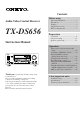
Contents Before using Audio Video Control Receiver TX-DS656 Important Safeguards ........................... 2 Precautions ........................................... 3 Features ................................................ 4 Supplied accessories ............................ 4 Before using this unit ........................... 5 Preparation Connection ........................................... 6 On-screen setting ............................... 18 Speaker system setup .........................
WARNING TO REDUCE THE RISK OF FIRE OR ELECTRIC SHOCK, DO NOT EXPOSE THIS APPLIANCE TO RAIN OR MOISTURE. CAUTION TO REDUCE THE RISK OF ELECTRIC SHOCK, DO NOT REMOVE COVER (OR BACK). NO USERSERVICEABLE PARTS INSIDE. REFER SERVICING TO QUALIFIED SERVICE PERSONNEL.
Precautions 1. Warranty Claim You can find the serial number on the rear panel. In case of warranty claim, please report this number. 2. Recording Copyright Recording of copyrighted material for other than personal use is illegal without permission of the copyright holder. 3. AC Fuse The fuse is located inside the chassis and is not user-serviceable. If power does not come on, contact your Onkyo authorized service station. 4.
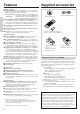
Features Supplied accessories Amplifier Features ■ 85 Watts Minimum of continuous RMS power to each of the five channels into 8Ω from 20 Hz to 20 kHz with no more than 0.
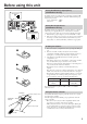
Before using this unit Setting the AM tuning step frequency (worldwide model only) AM FREQUENCY STEP Worldwide models are equipped with a switch that controls the AM band tuning steps. Set this switch to match the AM band tuning step frequency in your area. U.S.A. and Canada : 10kHz Other areas : 9kHz 10kHz 9kHz MJ 27122482 Setting the voltage selector (worldwide model only) VOLTAGE SELECTOR 220-230V 120V Worldwide models are equipped with a voltage selector to conform with local power supplies.
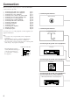
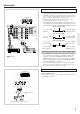
Connection This section describes, step by step, how to connect the TX-DS656 to your home theater components. 1 2 3 4 5 6 7 8 9 0 A B C D Connecting analog audio source equipment Connecting digital audio source equipment Connecting video source equipment Connecting a video camera or TV game machine Connecting a decoder with 5.
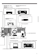
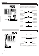
3 Connecting video source equipment 6 Connecting video recording equipment 2 Connecting digital audio source equipment CD player, DAT deck or MD recorder Video cassette recorder 5 Connecting a decoder with 5.1-channel output Decoder with 5.1-ch output 3 Connecting video source equipment DVD player A Connecting speakers MJ L R V IN R L R L SURROUND OUT VIDEO-2 CENTER DVD L MONITOR OUTPUT V (REC) R OUT R CAUTION: SPEAKER IMPEDANCE 6 OHMS MIN.
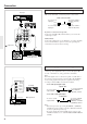
Connection 1 Connecting analog audio source equipment CD player Connect your audio source equipment, such as a turntable, CD player, MD recorder, DAT deck, or cassette tape deck, as shown below. Audio connection cable OUT MJ L R V SURROUND SPEAKERS OUT SURROUND IN L R OUT CENTER SPEAKER FRONT MAIN SPEAKERS FRONT L R IN (White) (Red) 27122482 S OUT VIDEO-1 ANTENNA R L R L R L MULTI CHANNEL OUT INPUT VIDEO-2 AM CENTER CAUTION: SPEAKER IMPEDANCE SUBWOOFER 6 OHMS MIN.
Connection 3 Connecting video source equipment • With a DVD player, video disc player, etc., that is equipped with at least one digital audio output terminal, its audio output can be connected to the TX-DS656 via an optical or coaxial cable (see the previous page). In this case, for recording or using the Multi-source function, it is also necessary that you connect the equipment via audio connection cables.
Connection 5 Connecting a decoder with 5.1-channel output TX-DS656 MJ L R V 27122482 S OUT IN FRONT MAIN SPEAKER SPEAKERS FRONT R L R L SURROUND IN OUT CENTER SURROUND SPEAKERS OUT VIDEO-1 ANTENNA R L R L R The TX-DS656's MULTI CHANNEL INPUT jacks can be used to connect a decoder equipped with 5.1-ch audio output (dts decoder, MPEG decoder, etc.). If you do so, use the V or S IN jack of the VIDEO-1/2/3 or DVD connector to connect the video or S-video connection cable.
Connection 7 Connecting audio recording equipment TX-DS656 MJ L R V FRONT MAIN SPEAKER SPEAKERS FRONT L R SURROUND IN L R OUT CENTER SURROUND SPEAKERS OUT IN Connect your audio recording equipment to the TAPE-1/2 OUT (REC) jacks. Digital recording is not possible, even if a DAT deck or MD recorder is connected. 27122482 S OUT VIDEO-1 ANTENNA R L R L R L MULTI CHANNEL OUT INPUT VIDEO-2 AM CENTER CAUTION: SPEAKER IMPEDANCE SUBWOOFER 6 OHMS MIN.
Connection 9 Connecting a TV/monitor TX-DS656 MJ L R V ANTENNA SURROUND IN L R OUT SPEAKER FRONT MAIN SPEAKERS FRONT L R IN CENTER SURROUND SPEAKERS OUT A TV or monitor equipped with a video input jack can be connected to the TX-DS656. 27122482 S OUT VIDEO-1 R L R L R L MULTI CHANNEL OUT INPUT VIDEO-2 AM CENTER CAUTION: SPEAKER IMPEDANCE SUBWOOFER 6 OHMS MIN.
Connection Indoor antenna Outdoor antenna 300 ohms ribbon wire 1 2 Connecting the antenna cable to the 75/300 ohm antenna adapter (worldwide models) Connecting a 300 ohm ribbon wire to the 75/300 ohm adapter: Loosen the screws and wrap the wire around them. Tighten the screws with a screwdriver. 3 ✦ ✦ ✦ ✦ ✦ ✦ ✦✦ ✦ ✦ ✦ 6 3 6 mm mm mm Slit B 15mm 1 Wire A 0 Connecting the antennas Slit C Connecting a coaxial : 1.
Connection U.S. and Canadian models Connecting the included antennas Other models Connecting the T-shaped FM antenna: ANTENNA ANTENNA AM AM FM 75 FM 75Ω FM 300Ω ANTENNA The T-shaped FM antenna is for indoor use only. Extend the antenna and move it in various directions until the clearest signal is received. Fix it with push pins or similar implements in the position that will cause the least amount of distortion.
Connection If bipolar type speakers are connected to the surround channels (Left front) L (Center) (Right front) C R SW A Connecting speakers On the rear panel of the TX-DS656, two sets of speaker terminals are provided; one for main-room speakers and the other for sub-room speakers. This section provides information on connecting the mainroom speakers. • For how to connect sub-room speakers, see "Multi-room system connections" on pages 46, 47.
Connection Connection for Front, Center, and Surround speakers Right Surround speaker Note: • Be sure to connect the Right and Left speakers to the receiver's corresponding speaker terminals. Also, be sure that you are connecting the speaker's positive (+) and negative (-) binding posts with the receiver's corresponding speaker terminals. Otherwise, inferior sound will result. • Use speakers whose nominal impedance is 6Ω.
C Using the AC outlets MJ L R V SURROUND SPEAKERS OUT IN SURROUND L R OUT OUT VIDEO-2 SPEAKERS CENTER R L R L R You can connect the power cord from other audio device to the rear of the TX-DS656. Since the AC outlets on the unit are the SWITCHED type, you can use the POWER button (or the SYSTEM button), or the POWER button on the remote controller to turn on/off the power to both the TX-DS656 and the connected audio devices.
On-screen setting If your TX-DS656 is connected to a TV set, you can perform various settings on the TV screen. This section shows you the basic operation of onscreen setting, as well as the method of changing the screen setup according to your preference. SMART SCAN CONTROLLER jog dial MASTER VOLUME Selecting the NTSC or PAL system (not available on U.S.
On-screen setting Selecting a Menu item 1 *** Menu *** Input Selector Rec Selector Surround Setup Screen Setup ENTER System Setup 2 *** Menu *** Input Selector Rec Selector Surround Setup Screen Setup ENTER System Setup 3 ** Screen Setup ** The on-screen setting is performed by using the cursor buttons and the ENTER button on the remote controller. This applies to all the setup items. In the following procedure, use the remote controller unless otherwise specified. 1. Press the ENTER button.
On-screen setting Setting the background color and superimpose mode (Screen Setup) 1 *** Menu *** Input Selector Rec Selector Surround Setup Screen Setup ENTER System Setup 2 *** Menu *** Input Selector Rec Selector Surround Setup Screen Setup ENTER System Setup 3 ** Screen Setup ** Background Color = BLUE-1 Superimpose Mode = NORMAL Immediate Display = ON ENTER Character Position 4 ENTER ENTER 5 ENTER 20 In the following procedure, you can set the background color of the Menu and setting s
Speaker system setup • Before performing speaker system setup, make sure that the speakers have been connected properly. • To get optimized surround effects, you need the correct speaker setting for your speaker system and listening environment. What is "System Setup"? In Speaker Setup, you perform the following three operations. You may use either the on-screen display or front panel switches.
Speaker system setup a On-screen speaker system setup *** Menu *** Input Selector Rec Selector Surround Setup Screen Setup System Setup b ** System Setup ** Speaker Setup Speaker Distance Level Calibration Starting the Test Signal. c * Speaker Setup * Subwoofer = YES Front = LARGE Center = SMALL Surround = SMALL You can enter the speaker distance in units of meters (m) or feet (ft). If "meters" is used, you can enter a distance within the range of 0.3m-9.0m in 0.3m increments.
Speaker system setup Speaker system setup using the front panel POWER (or SYSTEM) button SMART SCAN CONTROLLER jog dial MASTER VOLUME SMART SCAN CONTROLLER PRESET SYSTEM TUNING SURROUND ENTER PARAMETER STAND-BY POWER ON OFF SPEAKERS MAIN REMOTE 3-D BASS MULTI SOURCE REC OUT DIGITAL AUDIO SELECTOR MULTI CH INPUT PTY/ TP MIDNIGHT THEATER Re-EQ DISPLAY CHARACTER AUTO TUN SCAN GROUP MIN MAX BASS TREBLE MEMORY FM MUTE / MODE CLEAR VIDEO 3 / VIDEO CAM INPUT PHONES DVD S VIDEO VIDEO
Speaker system setup Level Calibration using remote controller SUBROOM A B LEARN SENDING/ LEARNED POWER button POWER DVD TAPE-1 SLEEP DIMMER TEST TONE SUR MODE MULTI-CH SOURCE SELECTOR INPUT VIDEO-1 VIDEO-2 VIDEO-3 TAPE-2 TUNER PHONO TEST TONE button CD PROGRAMMABLE AREA TV / VIDEO POWER CH VOLUME POWER TV/ VCR GROUP DISC SUBTITLE ON / OFF CD TUNER PRESET TAPE DVD PAUSE / STEP LEVEL y/u button CH SEL CURSOR ENTER LEVEL VOLUME MUTING / REMOTE SPEAKER REMOTE CONTROLLER 24
Input source selection and surround setup Before you can enjoy music or movies, you must select an input source and perform surround setups. This can be done in one of the following three ways: • Display the Menu on the TV screen and use the cursor buttons and ENTER button on the remote controller. • Use the unit's front panel operation buttons. • Use the remote controller operation buttons For how to play source equipment connected to the MULTI CHANNEL INPUT connector, see page 29.
Input source selection and surround setup 5. Select the input source(s) using the a or s cursor button. The input sources you can select are same as those you can select by using the input selector buttons on the front panel.
Input source selection and surround setup 1 7 5,6 5 6 MASTER VOLUME SMART SCAN CONTROLLER PRESET SYSTEM TUNING SURROUND ENTER PARAMETER STAND-BY POWER ON OFF SPEAKERS MAIN REMOTE 3-D BASS MULTI SOURCE REC OUT DIGITAL AUDIO SELECTOR MULTI CH INPUT PTY/ TP MIDNIGHT THEATER Re-EQ DISPLAY CHARACTER AUTO TUN SCAN GROUP MIN MAX BASS TREBLE MEMORY FM MUTE / MODE CLEAR VIDEO 3 / VIDEO CAM INPUT PHONES DVD S VIDEO VIDEO VIDEO-1 VCR-1 VIDEO-2 VCR-2 / TV VIDEO-3 CAM TAPE-1 MD TAP
Input source selection and surround setup SUBROOM A B LEARN SENDING/ LEARNED 1 2 POWER DVD SLEEP DIMMER TEST TONE SUR MODE MULTI-CH SOURCE SELECTOR INPUT VIDEO-1 VIDEO-2 VIDEO-3 TAPE-1 TAPE-2 TUNER PHONO 5 CD PROGRAMMABLE AREA TV / VIDEO POWER CH VOLUME POWER TV/ VCR GROUP CD DISC TUNER PRESET TUNER section TAPE DVD SUBTITLE ON / OFF PAUSE / STEP CH SEL 4 CURSOR ENTER LEVEL VOLUME MUTING / REMOTE SPEAKER REMOTE CONTROLLER Using the remote controller You can use the remo
Input source selection and surround setup 1 Playing the input source connected to the MULTI CHANNEL INPUT connector MASTER VOLUME SMART SCAN CONTROLLER PRESET Using the front panel or the remote controller: SYSTEM TUNING SURROUND ENTER PARAMETER STAND-BY 1. Press the POWER (or SYSTEM) button. The STAND-BY indicator on the front panel goes out and the display lights up.
Input source selection and surround setup Selecting the digital/analog audio input You can select the DIGITAL INPUT connector to which the digital audio input source is connected using the on-screen display or the front panel switches. The setting will be recalled automatically every time the same digital audio input source is selected.
Input source selection and surround setup Useful functions for playback BASS TREBLE 3-D BASS Adjusting the tone The BASS and TREBLE controls only affect the Left and Right front speakers; the 3-D BASS control affects the Left/Right front speakers plus the Center speaker. BASS: Adjust to strengthen or weaken bass response. TREBLE: Adjust to strengthen or weaken treble response. 3-D BASS: Use to enhance reproduction of ultra-low frequencies.
Listening to FM/AM broadcasts Tuning in a broadcasting station You can use one of the following two methods to listen to FM/AM broadcasts with the TX-DS656's built-in tuner. • Tune in a broadcasting station - Tune in an FM/AM station by specifying the frequency (Manual tuning) - Automatically tune in an FM station (Auto tuning) • Recall a preset broadcasting station You can name preset stations so that you can easily find the desired station.
Listening to FM/AM broadcasts Recalling a preset broadcasting station If you preset favorite broadcasting stations, you will be able to select them by using the on-screen Menu and/or the remote controller. You can preset a total of 30 FM and AM stations in three groups. Each of the groups (A, B, and C) can store up to 10 stations.
Listening to FM/AM broadcasts Recalling a preset station SUBROOM A B LEARN SENDING/ LEARNED POWER DVD TAPE-1 SLEEP DIMMER TEST TONE TAPE-2 TUNER PHONO CD TUNER PROGRAMMABLE AREA TV / VIDEO POWER CH VOLUME POWER TV/ VCR GROUP DISC SUBTITLE ON / OFF Using the remote controller: 1. Press the TUNER button in the SOURCE SELECTOR area. 2. Press the TUNER GROUP button repeatedly until the desired group is displayed. 3. Press the PRESET a or s button.
Listening to FM/AM broadcasts Entering a station name Characters which can be entered: SMART SCAN CONTROLLER jog dial ENTER button ABCDEFGHIJKLMNOPQRSTU VWXYZ"&,()*+,-./=?[ ]|012 3456789 Note: indicates a space.
Receiving RDS broadcasts (European models only) RDS reception is available only on the European model, and only in areas where RDS broadcasts are available. What is RDS? Many FM radio stations now transmit RDS signals which give additional information. RDS provides you with various services so that, for example, you can choose a station broadcasting your favorite categories of music or other information. (Refer to the right column for information details.
Receiving RDS broadcasts (European models only) SMART SCAN CONTROLLER jog dial TUNING button MASTER VOLUME SMART SCAN CONTROLLER PRESET SYSTEM TUNING SURROUND ENTER PARAMETER STAND-BY POWER ON OFF SPEAKERS MAIN REMOTE 3-D BASS REC OUT DIGITAL AUDIO SELECTOR MULTI SOURCE MULTI CH INPUT PTY/TP MIDNIGHT THEATER Re-EQ DISPLAY CHARACTER AUTO TUN SCAN GROUP MIN MAX BASS TREBLE MEMORY FM MUTE / MODE CLEAR VIDEO 3 / VIDEO CAM INPUT PHONES DVD S VIDEO VIDEO VIDEO-1 VCR-1 VIDEO-2 VCR
Using the Surround modes The TX-DS656 provides a variety of surround effects, enabling you to enjoy the feeling of a movie theater, concert hall or studio in your room. To get optimized surround sounds, your speaker system plays an important role. For how to connect and setup speakers, see "Connecting speakers" (on page 15) and "Speaker system setup" (on page 21). DSP (Digital Signal Processor) The DSP converts the musical signal into digital form and produces reflected sound from the digital signal.
Using the Surround modes Selecting a Surround mode a Using the on-screen Menu *** Menu *** For how to use the on-screen Menu, see "Selecting a Menu item" on page 19. 1. Press the ENTER button. The Menu appears on the TV screen. (a) 2. Select "Surround Setup" using the y or u cursor button and then press the s cursor button to display the Surround Setup screen. (b) 3. Select the desired surround mode parameter using the y or u cursor button and enter the setting using the a or s cursor button.
Using the Surround modes Changing the surround mode parameters Each surround mode is made up of a number of parameters. These parameters can be changed to optimize the reproduced surround sound according to your room size, listening environment, playback source type, taste, etc. Once parameters are set, they will be recalled automatically every time the same surround mode is selected. The parameters available in each surround mode vary depending on the surround mode.
Using the Surround modes Surround modes for music and sports Parameter HALL LIVE ARENA STUDIO Hall Size Effect Level Reverb Level Selecting the Hall size SMART SCAN CONTROLLER jog dial SURROUND button MASTER VOLUME SMART SCAN CONTROLLER PRESET SYSTEM TUNING SURROUND ENTER PARAMETER STAND-BY In the HALL, LIVE, ARENA, and STUDIO surround modes, you can choose the size of the virtual concert hall or studio from the following three levels: LARGE, MIDDLE, or SMALL (the default setting is MIDDLE).
Recording from a source • From the TX-DS656's output jacks, playback signals of the selected recording source equipment are continuously output during recording. • Use the on-screen display or the front panel to select the recording source and recording equipment. • The recording source, once set, will not change even if you change the input source by using the source selector buttons. Therefore, you can playback from one audio or video source while recording from another recording source.
Recording from a source Using the front panel 1. Press the REC OUT button. The REC OUT indicator flashes for 8 seconds. Display SPEAKERS MAIN V- SURROUND MODE HALL 3-DB STEREO 1 REC OUT ENTER Flashing 2. While the REC OUT indicator is flashing, select the recording source using the source selector buttons. The REC OUT indicator and the selected recording source name flash.
Using the TAPE-2 MONITOR function Playing equipment connected to the TAPE-2 jacks Playing equipment connected to the TAPE-2 jacks does not differ from playing equipment connected in other ways. See "Input source selection and surround setup" on page 25. How does the TAPE-2 MONITOR button differ from other source selector buttons? In addition to selecting the TAPE-2 source, the TAPE-2 MONITOR button has a special feature for recording with a 3-head cassette tape deck.
Using the other remote controller functions with the supplied remote controller The remote controller supplied with the TX-DS656 can learn functions available with other component's remote controllers. SENDING/ LEARNED indicator The control codes for Onkyo cassette tape decks and CD players are already available with the supplied remote controller.
Multi-room system connections U.S.A. and Canadian models (Xantech Multi-Room Systems) Do not plug in the power cord until all connections have been made. When making connections 1 through 5, be sure to connect the units as shown in the diagram below. Do not make a mistake when connecting the units. A. Operating components displaying Onkyo's z mark from the sub-room Components mounted in a rack should be connected as shown below to enable remote control operation. MAIN ROOM 1.
Multi-room system connections Models other than U.S.A. and Canadian models (Onkyo Multi-Room Systems) Do not plug in the power cord until all connections have been made. When making connections 1 through 4, be sure to connect the units as shown in the connection diagram below. Do not make a mistake when connecting the units. A. Operating components displaying Onkyo's z mark from the sub-room Components mounted in a rack should be connected as shown below to enable remote control operation. MAIN ROOM 1.
Multi-room system connections Playing a source in the sub-room SPEAKERS REMOTE MASTER VOLUME SMART SCAN CONTROLLER PRESET SYSTEM TUNING SURROUND ENTER PARAMETER STAND-BY POWER ON OFF SPEAKERS MAIN REMOTE 3-D BASS MULTI CH INPUT MIDNIGHT THEATER Re-EQ MULTI SOURCE REC OUT DIGITAL AUDIO SELECTOR PTY/ TP DISPLAY CHARACTER AUTO TUN SCAN GROUP MIN MAX BASS TREBLE MEMORY FM MUTE / MODE CLEAR VIDEO 3 / VIDEO CAM INPUT PHONES DVD S VIDEO VIDEO VIDEO-1 VCR-1 VIDEO-3 CAM VIDEO-2 VCR
Memo 49
Troubleshooting Note: If a problem occurs while you are using the remote controller, first operate the unit using the front panel controls to confirm that it is not due to a malfunction (or worn out batteries) of the remote controller. Trouble Cause Power shut off immediately after power on. • Amplifier protection circuitry has been activated. No power • Power cord is disconnected. • There is external noise in the computer circuits of the TX-DS656. Power but no sound • AC fuse is blown.
Troubleshooting Trouble Cause Remedy AM stations cannot be received. • AM loop antenna is not attached. • Connect the included AM loop antenna to the AM antenna connectors. Buzzing noise on AM (particularly conspicuous at night or with weak stations) • Noise from electrical apparatus such as fluorescent lamp • Move AM loop antenna to a different position. • Set up outdoor AM antenna.
Specifications AMPLIFIER SECTION Continuous Average Power output (FTC) Front Main L/R channels: 85 watts per channel min. RMS at 8 ohms, both channels driven from 20Hz to 20kHz with no more than 0.08% total harmonic distortion. Center channel: 85 watts min. RMS at 8 ohms, driven from 20Hz to 20kHz with no more than 0.08% total harmonic distortion. Surround L/R channels: 85 watts per channel min. RMS at 8 ohms, both channels driven from 20Hz to 20kHz with no more than 0.08% total harmonic distortion.
Control positions and names Rear panel MJ L R V IN R L R L SURROUND OUT VIDEO-2 CENTER DVD MONITOR OUTPUT V (REC) OUT TAPE-1 R L R L (REC) GND CAUTION: SPEAKER IMPEDANCE 6 OHMS MIN. / SPEAKER FRONT REMOTE SPEAKERS AC 120V 60Hz SWITCHED TOTAL 120W 1A MAX.
Control positions and names Front panel 1 2 3 4 5 6 7 8 9 10 11 12 MASTER VOLUME SMART SCAN CONTROLLER PRESET SYSTEM TUNING SURROUND ENTER PARAMETER STAND-BY POWER ON OFF SPEAKERS MAIN REMOTE 3-D BASS REC OUT DIGITAL AUDIO SELECTOR MULTI SOURCE MULTI CH INPUT PTY/TP MIDNIGHT THEATER Re-EQ DISPLAY CHARACTER AUTO TUN SCAN GROUP MIN MAX BASS TREBLE MEMORY FM MUTE / MODE CLEAR VIDEO 3 / VIDEO CAM INPUT PHONES DVD S VIDEO VIDEO VIDEO-1 VCR-1 VIDEO-2 VCR-2 / TV VIDEO-3 CAM
Control positions and names Display Display h a b c d SPEAKERS MAIN REMOTE TAPE-2 MONITOR V-DVD123 DIGITAL 123 f e SURROUND MODE OFF HALL DOLBY DIGITAL STUDIO LIVE PRO LOGIC 3STEREO ARENA g CINEMA Re-EQ 3-DB MIDNIGHT THEATER MUTING SLEEP dB IPM ch MIN kHz MHz k l j mn FM MUTE STEREO AUTO TUNED RDS MEMORY REC OUT MULTISOURCE r q p o u t v i s If a protective film on the surface of the display makes it difficult to read the display, remove the protective film. a.
Sales & Product Planning Div.: 2-1, Nisshin-cho, Neyagawa-shi, OSAKA 572-8540, JAPAN Tel: 0720-31-8111 Fax: 0720-33-5222 ONKYO U.S.A. CORPORATION 200 Williams Drive, Ramsey, N.J. 07446, U.S.A. Tel: 201-825-7950 Fax: 201-825-8150 E-mail: onkyo@onkyousa.com ONKYO EUROPE ELECTRONICS GmbH Industriestrasse 20, 82110 Germering, GERMANY Tel: 089 84 93 20 Fax: 089 84 93 226 E-mail: info@onkyo.