Contents Before using Inportant Safeguards ........................................ 2 AV Receiver Precautions ....................................................... 3 Features ............................................................ 4 Supplied accessories ........................................ 4 TX-DS595 Before using this unit ...................................... 5 Facilities and connections Front panel facilities ........................................ 6 Remote controller ...................
WARNING: TO REDUCE THE RISK OF FIRE OR ELECTRIC SHOCK, DO NOT EXPOSE THIS APPLIANCE TO RAIN OR MOISTURE. CAUTION: TO REDUCE THE RISK OF ELECTRIC SHOCK, DO NOT REMOVE COVER (OR BACK). NO USER-SERVICEABLE PARTS INSIDE. REFER SERVICING TO QUALIFIED SERVICE PERSONNEL.
21. Replacement Parts – When replacement parts are required, be sure the service technician has used replacement parts specified by the manufacturer or have the same characteristics as the original part. Unauthorized substitutions may result in fire, electric shock, or other hazards. 22. Safety Check – Upon completion of any service or repairs to the appliance, ask the service technician to perform safety checks to determine that the appliance is in proper operation condition. 23.
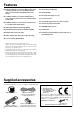
Features ■ 75 Watts minimum of continuous RMS power to each of the five channels into 8 Ω from 20 Hz to 20 kHz with no more than 0.08% THD (USA models, FTC rating) ■ 110 Watts minimum of continuous RMS power to each of the five channels into 6 Ω at 1 kHz (European models, DIN) ■ Non-Scaling Configuration ■ Cinema Re-EQTM ■ Late night mode (high, low, off) ■ 5.
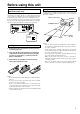
Before using this unit Setting the Voltage selector (Worldwide models only) Using the remote controller Worldwide models are equipped with a voltage selector to conform with local power supplies. Be sure to set this switch to match the voltage of the power supply in your area before plugging in the unit. Determine the proper voltage for your area: 220-230 V or 120 V. If the preset voltage is not correct for your area, insert a screwdriver into the groove in the switch.
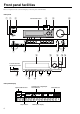
Front panel facilities Here is an explanation of the controls and displays on the front panel of the TX-DS595.
Front panel facilities For operational instructions, see page indicated in brackets [ ]. POWER switch [16] Turns on and off the main power supply for the TX-DS595. STANDBY indicator [16] Lights when the TX-DS595 is in the standby state and flashes when a signal is received from the remote controller. STANDBY/ON button [16] Press to turn on the TX-DS595 when in the standby state. Press again to return the TX-DS595 to the standby state.
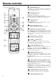
Remote controller 1 SEND/LEARN indicator This indicator acts as a guide when commands are programmed into or sent by the remote controller. It also warns the user when an error is made or battery power is low. SEND / LEARN PREP 2 3 4 S MED & LEARNING CAPA BILITY ON/STDBY button [16] MACRO EC T MO DE MODE MD VR CABL VCR E TV T SA RE 7 TU R SET UP N CH DISC VOL 8 C TO H S E PM L ENU AUDIO 0 E SLEEP button [26] Sets the sleep function.
Remote controller Selects an input source. Same as the input selector buttons on front panel of the TX-DS595. The input source for each buttons is given here. DVD:DVD, CD:CD, V1:VIDEO1, V2:VIDEO2, V3:VIDEO3, V4:Not used with the TXDS595, T1:TAPE, T2:Not used with the TX-DS595, TUN:FM/AM, PH:PHONO. Numeric key/Listening mode selector/SP A, B/ Re-EQ/DISPLAY/DIMMER buttons 1 to 9, +10, --/---, 0: For entering the number of a track. STEREO, DIRECT, DSP / , SURR, A.ST: You can select a listening mode.
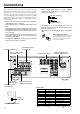
Connections Here is explanation of how to connect the main components to the TX-DS595 in the standard manner. There are many ways that any one component can be connected, and it is up to you to decide which method best fits your situation. The directions given here are only one option and should only be thought of as such. It is best to fully understand the nature of each connector and terminal as well as each of your components and their features to ascertain which method of connection is best.
Connections : Signal flow Audio connection cable Left (White) L Right (Red) R Analog audio output L (White) R (Red) 2. CD player (CD) Digital audio output (optical) ANTENNA AM MONITOR OUT Analog audio output L (White) 1.
Connections MONITOR OUT VIDEO 1 DVD IN Video output VIDEO 2 VIDEO 3 V IN IN IN OUT VIDEO VIDEO S video REMOTE CONTROL 4. DVD player (DVD) NO CD L (White) IN L S video output S video output S VIDEO S VIDEO TAPE OUT Video output Analog audio output R R R (Red) L (White) FRONT L SURR CENTER OPTICAL 1 COAXIAL 2 1 Digital audio output (Coaxial) Analog audio output R (Red) 2 R ER Digital audio output (Coaxial) UT MULTI CHANNEL INPUT 5.
Connections If the device has a digital output jack as well, be sure to also connect it to either a DIGITAL INPUT (COAXIAL) or DIGITAL INPUT (OPTICAL) jack on the TX-DS595 depending on the type of connector on the device. With the initial settings of the TX-DS595, the VIDEO 1 input source is set for digital input at the COAXIAL 2 jack. If the digital connection is made at a different jack, this must be changed at the setup menu: Input Setup → Audio Setup → Digital Input (see page 29). 6.
Connections Connect to devices with multichannel output By connecting a DVD player, MPEG decoder, or other component that has a multi channel port, you can playback the audio with 5.1 channel output. So, be sure to prepare a cable that can properly connect the TX-DS595 to the peripheral device.
Connecting speakers • Be sure to connect the positive and negative cables for the speakers properly. If they are mixed up, the left and right signals will be reversed and the audio will sound unnatural. • Do not connect more than one speaker cable to one speaker terminal. Doing so may damage the TX-DS595. • Use FRONT SPEAKERS B terminals to connect a second pair of front speakers. • When you listen to surround audio or select Multichannel, be sure to turn on SPEAKERS A. Connecting speakers 1.
Connecting the power SEND/LEARN indicator STANDBY indicator ON STANDBY/ON SEND / LEARN R PREP S LE O G RA M M E D & LEARNING CAP ABILIT Y STDBY STDBY ON EP MACRO D IR RCVR MODE EC T R CH LEVEL MASTER VOLUME E VCR N SET UP C TO H SEL PM ENU T TES U MEN CA BL TV T SA TU R CH DISC STANDBY/ON DSP / MODE ADJ DVD MD RE A SPEAKERS B MO DE MODE CD R CV VOL SETUP AUDIO STANDBY MUTING RETURN SUBTITLE ANGLE POWER TV / VCR LEVEL PUSH TO ENTER ON OFF DISPLAY RT / PTY/ TP
Connecting antennas To use the tuner of TX-DS595, it is necessary to prepare the supplied FM and AM antennas. • Adjustment and placement of the FM and AM antennas for better reception must be done while listening to a station broadcast. • If better reception cannot be obtained, then placement of an outside antenna is recommended. Assembling the AM loop antenna Assemble the loop antenna as shown in the illustration.
Connecting antennas Connecting an FM outdoor antenna Please make sure that you follow the considerations: • Keep the antenna away from noise sources (neon signs, busy roads, etc.). • It is dangerous to put the antenna close to power lines. Keep it well away from power lines, transformers, etc. • To avoid the risk of lightning and electrical shock, grounding is necessary. Follow item 14 of the “Important Safeguards” on page 2 when you install the outdoor antenna.
Speaker setup Follow the steps below before you start operating the unit.
Speaker setup Speaker Distance Level Calibration These settings tell the TX-DS595 how far away your speakers are located from the listening position so that it can provide the optimum sound space. If you are continuing from setting the speaker configuration and are still in the setup mode, skip directly to step 2. These settings allow you to set the volume levels of each speaker individually so that they all sound at the same level when heard from the listening position.
Listening to Radio Broadcasts TUNING / FM MODE A SPEAKERS B CH LEVEL MASTER VOLUME STANDBY/ON DSP / MODE ADJ SETUP STANDBY RETURN POWER PUSH TO ENTER ON OFF DISPLAY RT / PTY/ TP FM MODE PRESET MEMORY DVD VIDEO 1 TUNING PRESET SMART SCAN NAVIGATOR BASS PHONES AUDIO SELECTOR VIDEO 2 VIDEO 3 TAPE FM AM PHONO TREBLE CD VCR AV RECEIVER TX-DS595 FM AM One of the features of the TX-DS595 that is most frequently used is its ability to play FM and AM broadcast radio stations.
Listening to Radio Broadcasts SEND / LEARN R PREP PRESET / SLE RCVR MODE CH LEVEL MASTER VOLUME CH STANDBY/ON DSP / MODE ADJ D & LEARNING CAP ABILIT Y STDBY ON EP MACRO D IR A SPEAKERS B OG RA MM E EC T R MO DE MODE DVD CD MD R CV CA BL VCR E TV T SA URN SET UP C TO H SEL PM ENU T TES U MEN T RE CH DISC VOL SETUP AUDIO STANDBY MUTING RETURN SUBTITLE ANGLE POWER TV / VCR LEVEL PUSH TO ENTER ON OFF DISPLAY RT / PTY/ TP FM MODE PRESET MEMORY DVD VIDEO 1 TUNI
Listening to RDS broadcasts (European models only) Listening to RDS broadcasts PTY program types in Europe RDS reception is available only on the European model and only in areas where RDS broadcasts are available. The text given in parenthesis is what is actually displayed on the TXDS595. What is RDS? RDS stands for Radio Data System and is a type of FM broadcasting. RDS was developed within the European Broadcasting Union (EBU) and is available in most European countries.
Listening to RDS broadcasts Jog dial RT/PTY/TP A SPEAKERS B CH LEVEL MASTER VOLUME STANDBY/ON DSP / MODE ADJ SETUP STANDBY RETURN POWER PUSH TO ENTER ON OFF DISPLAY RT / PTY/ TP FM MODE PRESET MEMORY DVD VIDEO 1 TUNING PRESET SMART SCAN NAVIGATOR BASS PHONES AUDIO SELECTOR VIDEO 2 VIDEO 3 TAPE FM AM PHONO TREBLE CD VCR AV RECEIVER TX-DS595 FM Displaying Radio Text (RT) If the station you are currently tuned into is broadcasting RT signals, they will be displayed in the front di
Enjoying music or videos with the TX-DS595 SEND / LEARN R PREP SPEAKERS A/B Jog dial DISPLAY A SPEAKERS B O G RA M M E D & LEARNING CAP ABILIT Y MASTER VOLUME STDBY ON EP SLE MACRO D IR CH LEVEL RCVR MODE MASTER VOLUME EC T RC MO DE MODE DVD CD MD VR E VCR N SET UP C TO H SEL PM ENU T TES U MEN CA BL TV T SA RE TU R STANDBY/ON DSP / MODE ADJ SETUP CH DISC VOL VOL STANDBY RETURN POWER AUDIO PUSH TO ENTER ON MUTING OFF SUBTITLE ANGLE DISPLAY DIMMER FM MODE PRESET
Enjoying music or videos with the TX-DS595 SEND / LEARN R PREP SPEAKERS A/B MASTER VOLUME Jog dial CH LEVEL DISPLAY A SPEAKERS B CH LEVEL SLEEP SLE O G RA M M E D & LEARNING CAP ABILIT Y STDBY ON EP MACRO D IR RCVR MODE MASTER VOLUME EC T RC MO DE MODE DVD CD MD VR E VCR N SET UP C TO H SEL PM ENU T TES U MEN CA BL TV T SA RE TU R STANDBY/ON DSP / MODE ADJ SETUP CH SEL STANDBY RETURN CH DISC VOL POWER AUDIO PUSH TO ENTER ON OFF DISPLAY DIMMER FM MODE PRESET MEMO
Enjoying music or videos with the TX-DS595 Changing the audio mode Enjoying the multichannel input Press the AUDIO SELECTOR button on the front panel (or the AUDIO button on the remote controller) to change the audio mode. Each time the button is pressed, the mode changes from “AUTO” → “MULTICH” → “ANALOG” and back to “AUTO.” The “AUTO” audio mode is recommended for normal circumstances.
Using listening mode The TX-DS595’s surround sound enables you to enjoy the presence of a movie theater or concert hall in your room. The configuration of the speakers are very important for the surround sound. Refer to “Connecting speakers” on page 15. Before using a listening mode, make sure the Speaker Setup parameters have been set (refer to page 19) . Once the parameters have been set, it is not necessary to set them again. Refer to page 25 for information regarding how to select the listening mode.
Input Setup SETUP 2. Input Setup 2. Press the SETUP button. These settings can be set differently for each input source. Turn the jog dial or press the and cursor buttons on the remote controller to display “2. INPUT SETUP.” Audio Setup Digital Input (D. INPUT): This setting tells the TX-DS595 which input source button on the front panel is connected with which digital input jack on the rear panel.
Input Setup 1. Select the desired input source. TX-DS595 DVD VIDEO 1 VIDEO 2 VIDEO 3 TAPE FM AM PHONO CD VCR 5. Turn the jog dial or press the or cursor buttons on the remote controller to select the listening mode. Refer to the table to see what listening modes are available. 6. Press either the jog dial or the cursor button on the remote controller. The listening mode when playing a digital format source with the currently selected input source appears. Remote controller 2.
Input Setup IntelliVolume When switching input sources, you may find that the output level for different components or input sources connected to the TX-DS595 is different even though the main volume setting is the same. Under normal circumstances, you would then have to change the volume setting each time you change the input source.
Preference 3. Preference 5. Press the RETURN button. “HEADPHONES LVL?” appears in the front display. Volume Setup To exit the setup mode immediately, press the SETUP button. Maximum Volume (MAXIMUM VOL): This setting allows you to set the maximum volume that can be output with the MASTER VOLUME dial to prevent components from being damaged by excessively loud volumes. When Maximum Volume is not set, set this to OFF.
Recording A SPEAKERS B CH LEVEL MASTER VOLUME STANDBY/ON DSP / MODE ADJ SETUP STANDBY RETURN POWER PUSH TO ENTER ON OFF DISPLAY RT / PTY/ TP FM MODE PRESET MEMORY DVD VIDEO 1 TUNING PRESET SMART SCAN NAVIGATOR BASS PHONES AUDIO SELECTOR VIDEO 2 VIDEO 3 TAPE FM AM PHONO TREBLE CD VCR AV RECEIVER TX-DS595 Input source buttons The TX-DS595 can also be used to record an input source media.
Using remote controller Overview The RC-447M remote controller is a useful tool to help you operate the components of your home theater. To do so, first press the Mode button that corresponds to the device you wish to control. Then simply press the desired operation button and the component will operate accordingly.
Using remote controller Controlling an Onkyo CD player The z connector of the Onkyo compact disc player must be connected to the TX-DS595 (see page 13).
Using remote controller Controlling an Onkyo DVD player The z connector of the Onkyo DVD player must be connected to the TX-DS595 (see page 13). 1. Press the DVD MODE button. The DVD MODE button lights green. 2. Press the desired operation button. The buttons shaded in the figure to the left are the operation buttons that can be used to control an Onkyo DVD player.
Using remote controller Controlling an Onkyo MD recorder The z connector of the ONKYO MD recorder must be connected to the TX-DS595 (see page 13). SEND / LEARN PR E P RO G RA M MED & LEARNING CAPA BILITY STDBY ON S LE STDBY ON EP MACRO DIR ECT DVD CD RC MO DE MODE MD VR CABL MD MODE VCR E 1. Press the MD MODE button. The MD MODE button lights green. 2. Press the desired operation button.
Learning a pre-programming code The remote controller has three learning functions. One is entering the signal number for a remote controller of another brand that is preprogrammed. Another is a normal learning function that enables the remote controller to learn the codes from other remote controllers. And the last is a macro learning function that enables you to program a series of operations into the remote controller so that the operations can all be performed at once by pressing one button.
Learning a pre-programming code Pre-programmong codes Note: If more than one code is given in the table, try the code one by one until you reach the code for your component (i.e. if the first code does not work, then try the next). DVD BRAND DENON HITACHI JVC KENWOOD MAGNAVOX MARANTZ MITSUBISHI ONKYO PANASONIC PIONEER PROSCAN RCA SONY TOSHIBA YAMAHA ZENITH SETTING No.
Operating your programmed remote controller After performing the procedure given above, the following modes become enabled for use. DVD MODE (DVD Player Mode) Buttons with programmed usage and operations are the same as the operational buttons on page 36. SAT MODE (Satellite Tuner Mode) 1. Press the SAT MODE button. The SAT button lights green.
Operating your programmed remote controller VCR MODE (VCR Mode) 1. Press the VCR MODE button. The VCR button lights green.
Programming the commands of remote controllers for other devices into the remote controller PE TA LE AR N G IN ITY BIL PA CA 5 to 15 cm (2 to 6 inches) C IS D D C ER M IM D PRE PRO GR AM ME D& -1 EO VID D C CH TI- T UL PU M IN RE SUOD M O N R O T TO H SE C P P ER E LE R N PR EE SE E TU T UN SL PU T R E IN P W E U P O O P R TA G VD D -2 EO VD D VID H C L SE ST E TEON T G TIN U M E M LU VO S 85 Programming procedure When programming the commands of another remote controller to the RC-447M re
Programming the commands of remote controllers for other devices into the remote controller 4. Press and hold down the button (that corresponds to the command you are programming) on the remote controller of the other device until the SEND/LEARN lamp on the remote controller flashes twice. After flashing twice, the SEND/LEARN indicator will light again. 5.
Programming the commands of remote controllers for other devices into the remote controller SEND/LEARN indicator SEND / LEARN PR E P S LE RO G RA M You can only erase memorized commands and not preset ones. MED & LEARNING CAPA BILITY STDBY ON EP MACRO DIR ECT R MO DE MODE DVD CD MD R CV CABL VCR E TV T SA RE MODE buttons SET UP N TU R CH DISC C TO H SEL PM EN U T TES U MEN MUTING SUBTITLE ANGLE TV / VCR LEVEL RANDOM 3. Press and release the same button again.
Using a Macro function What is a Macro function? Programming a Macro function A Macro function enables you to program a series of button operations (up to 16) on the remote controller into a single button. For example, to play a compact disc player connected to the TXDS595 normally, you must perform the following steps: 1. Press the RCVR MODE button. 2. Press the ON button. 3. Press the CD (INPUT SELECTOR) button. 4. Press the CD MODE button. 5. Press the playback ( ) button.
Using a Macro function Programming the Direct Macro function SEND / LEARN PR EP R O G RA M MED & LEARNING CAPA BILITY ON S LE STDBY ON EP MACRO DIRECT MACRO DIR ECT MO DE MODE MD VR CABL VCR E MODE buttons TV T SA RE RCVR MODE CD MODE DVD CD RC T SET UP URN CH DISC VOL C TO H SEL PM EN U AUDIO T TES U MEN MUTING SUBTITLE ANGLE TV / VCR LEVEL (CD playback) RANDOM OPEN / CLOSE REC INPUT SELECTOR DVD CD V1 V3 V4 TUN STEREO DIRECT 1 2 SURR T2 T1 V2 A.
Using a Macro function Erasing a macro from the MODE MACRO button SEND / LEARN PR E P S LE RO G RA M MED & LEARNING CAPA BILITY STDBY ON EP MACRO DIR ECT MODE buttons MO DE MODE DVD CD RC MODE MACRO MD VR CABL VCR E TV T SA T RE SET UP URN CH DISC 2. Press the MODE MACRO button again. The SEND/LEARN indicator flashes twice slowly. The macro programmed to the MODE button pressed in Step 1 above is erased. VOL C TO H SEL PM EN U AUDIO 1.
Using a Macro function Erasing all commands and macros that have been programmed SEND / LEARN PR E P RO G RA M This procedure will erase all the commands and macros that you have programmed into the remote controller and return it to its default settings. This operation will not affect the preset settings of the remote controller. MED & LEARNING CAPA BILITY STDBY ON S LE STDBY ON EP MACRO DIR ECT MO DE MODE DVD CD RC MD VR CABL 1.
Specifications AMPLIFIER SECTION Continuous Average Power output (FTC) All channels: 75 W per channel min. RMS at 8 Ω, 2 channels driven from 20 Hz to 20 kHz with no more than 0.08% total harmonic distortion. 100 W min. RMS at 6 Ω, 2 channels driven from 1 kHz with no more than 0.1% total harmonic distortion. Continuous Power output (DIN) 110 W at 6 Ω Maximum Power output (EIAJ) 140 W at 6 Ω Dynamic Power Output (Stereo) 2 × 210 W at 3 Ω 2 × 155 W at 4 Ω 2 × 90 W at 8 Ω Total Harmonic Distortion: 0.
Troubleshooting guide If a problem occurs while you are using the remote controller, first try to operate the controls on the front panel of the TX-DS595 to make sure that it is not due to a malfunction (or worn out batteries) in the remote controller. POWER Power shuts off immediately after power on. • Amplifier protection circuitry has been activated. ➞ Remove the power cord from outlet immediately. Contact your Onkyo service center. No power. • Power cord is disconnected. ➞ Connect power cord.
Troubleshooting guide No preset station is recalled. • Power cord has been unplugged or the POWER switch has been turned off for a long time. ➞ The memory contents are lost. Store all stations again. VIDEO and AUDIO Desired picture does not appear. • Improper connection. ➞ Check the connection again. Insert the plugs and connectors completely. Picture and sound do not match. • Improper connection. ➞ Check connections. No sound, or sound of the selected source is not heard.
Sales & Product Planning Div. : 2-1, Nisshin-cho, Neyagawa-shi, OSAKA 572-8540, JAPAN Tel: 072-831-8111 Fax: 072-833-5222 ONKYO U.S.A. CORPORATION 18 Park Way, Upper Saddle River, N.J. 07458, U.S.A. Tel: 201-785-2600 Fax: 201-785-2650 E-mail: onkyo@onkyousa.com ONKYO EUROPE ELECTRONICS GmbH Industriestrasse 20, 82110 Germering, GERMANY Tel: 089-849-320 Fax: 089-849-3265 E-mail: info@onkyo.de ONKYO CHINA LIMITED Units 2102-2107, Metroplaza Tower I, 223 Hing Fong Road, Kwai Chung, N.T.