Contents Before using AV Receiver TX-DS575X Instruction Manual Important Safeguards........................ 2 Precautions ....................................... 3 Features............................................. 4 Supplied accessories......................... 4 Before operating this unit ................. 5 Preparation Audio equipment connections .......... 6 Video equipment connections .......... 7 Connecting other devices ................. 8 Connecting speakers.......................
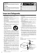
WARNING: TO REDUCE THE RISK OF FIRE OR ELECTRIC SHOCK, DO NOT EXPOSE THIS APPLIANCE TO RAIN OR MOISTURE. WARNING AVIS RISK OF ELECTRIC SHOCK DO NOT OPEN RISQUE DE CHOC ELECTRIQUE NE PAS OUVRIR The lightning flash with arrowhead symbol, within an equilateral triangle, is intended to alert the user to the presence of uninsulated “dangerous voltage” within the product’s enclosure that may be of sufficient magnitude to constitute a risk of electric shock to persons.
Precautions 1. Warranty Claim You can find the serial number on the rear panel of this unit. In case of warranty claim, please report this number. 2. Recording Copyright Recording of copyrighted material for other than personal use is illegal without permission of the copyright holder. 3. AC Fuse The fuse is located inside the chassis and is not user-serviceable. If power does not come on, contact your Onkyo authorized service station. 4.
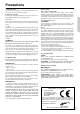
Features Supplied accessories 70 WATTS MINIMUM of continuous RMS power to each of the five channels into 8Ω from 20 Hz to 20 kHz with no more than 0.08 % THD (USA models, FTC rating) ■ 100 WATTS MINIMUM of continuous RMS power to each of the five channels into 6Ω at 1 kHz (European models, DIN) ■ 130 WATTS MINIMUM to each of the five channels into 6Ω at 1 kHz (Asian models, EIAJ ) ■ WRAT — WIDE RANGE AMPLIFIER TECHNOLOGY ■ DTS®*, DOLBY®** DIGITAL AND DOLBY® PRO LOGIC DECODERS ■ 5.
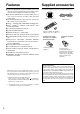
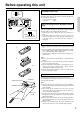
Before operating this unit Setting the AM tuning step frequency (Worldwide models only) 10kHz 9kHz Worldwide models are equipped with a switch that controls the AM band tuning steps. Please set this switch to match the AM band tuning step frequency in your area. U.S.A.
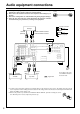
Audio equipment connections • On each pair of input jacks, a red connector (marked R) corresponds to the right • • • Audio connection cable channel, and a white connector (marked L) to the left channel. Please refer to the instruction manual of each component when making any connections. This receiver is designed for use with turntables using moving magnet cartridges. Insert the plugs and connectors securely.
Video equipment connections • On each pair of input jacks, a red connector (marked R) corresponds to the right • • Audio connection cable channel, and a white connector (marked L) to the left channel. A yellow connector (marked V) is used for video connection. Please refer to the instruction manual of each component when making any connections.
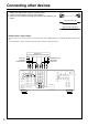
Connecting other devices • On each pair of input jacks, a red connector (marked R) corresponds to the right • • Audio connection cable channel, and a white connector (marked L) to the left channel. A yellow connector (marked V) is used for video connection. Please refer to the instruction manual of each component when making any connections. L (Left) L R (Right) R Video connection cable V (Video) V Monaural audio cable (mono) Decoder with 5.1 channel output You may connect the 5.
Connecting other devices AC outlet connection DIGITAL INPUT FRONT SPEAKERS B COAXIAL 2 WARNING AVIS RISK OF ELECTRIC SHOCK DO NOT OPEN RISQUE DE CHOC ELECTRIQUE NE PAS OUVRIR R V L L L R R COAXIAL 1 S FRONT SPEAKERS ANTENNA DVD IN VIDEO 3 IN A AM VIDEO 2 L L R R OPTICAL 2 OPTICAL 1 IN CENTER SPEAKER FM 75 AC OUTLETS REMOTE CONTROL IN VIDEO 1 GND V IN R MONITOR OUT S L SURROUND L R AV RECEIVER TAPE L MODEL NO.
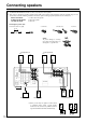
Connecting speakers • If you want to use the surround effects, connect surround speakers. For the best results, connect a center speaker. • Use FRONT SPEAKERS B terminals to connect a second pair of front speakers. • This receiver is designed to produce optimum sound quality when speakers with impedances within the specified ranges are connected. Please check the following information and choose speakers with appropriate impedances for the connections. FRONT SPEAKERS: A or B: 6 ohms min.
Positioning speakers Positioning speakers Speaker placement plays an important role in the reproduction of Surround sound. The placement of the speakers varies depending on the size of the room and the wall coverings used in the room. The illustration shows an example of a layout for standard speaker placement. Refer to this example when you position the speakers in order to experience the best of Surround sound.
Making antenna connections Outdoor antenna Indoor antenna 300 ohms ribbon wire 1 2 3 ✦ ✦ ✦ ✦ ✦ ✦ ✦✦ ✦ ✦ ✦ 6 3 6 mm mm mm Slit B 15mm 1 Wire A Connecting the antenna cable to the 75/300 ohm antenna adapter (Non-U.S., Canadian and European models) Connecting the 300 ohm ribbon wire: Loosen the screws and wrap the wire around these screws. Then tighten the screws with a screwdriver. Connecting the coaxial cable: 1.
Making antenna connections U.S. and Canadian models Other models ANTENNA Connecting the included antennas Connecting the FM indoor antenna: The FM indoor antenna is for indoor use only. Extend the antenna and move it in various directions until the clearest signal is received. Fix it with push pins or similar implements in the position that will cause the least amount of distortion. If the reception is not very clear with the attached FM indoor antenna, the use of an outdoor antenna is recommended.
Speaker setup Follow the steps below before you start operating the unit.
Speaker setup 4 or PRESET / MODE ADJ DOWN UP ENTER or ENTER / SCAN or 5 or PRESET / MODE ADJ DOWN UP ENTER or ENTER / SCAN or 4. Select the size of the center speaker. Pressing the PRESET/MODE ADJ √/® buttons switches among “LARGE,” “SMALL,” and “NONE.” Note: If you have selected “SMALL” for the front speakers, you can select only “SMALL” or “NONE” for the center speaker. LARGE: When a large speaker is used as the center speaker. SMALL: When a small speaker is used as the center speaker.
Speaker setup 1. MODE AUDIO button 3. CH SEL button 2. VOL q/u buttons 2. TEST button 4. 3. LEVEL +/– buttons Test Tone 1 Use the remote controller and produce the test tone to adjust the level of the connected speakers. 1. Press the MODE AUDIO button. 2. Press the TEST button. Press the VOL q button repeatedly to gradually raise the volume to an appropriate level.
Selecting a sound source Follow the steps below to select a device to play the sound source. PTY/TP button (European models only) (Refer to page 27) 2. Make sure that the SPEAKERS A indicator is lit on the display. If it is not lit, press the SPEAKERS A button. (Refer to the “Speakers selector” section on the page 20 for more details.) DIMMER button (other than European models) Use this button to change the brightness of the display (normal or dim). 5. Adjust the volume to an appropriate level.
Selecting a sound source TX-DS575X Assigning the digital input/Selecting the input signal format DIGITAL INPUT DVD Player COAXIAL 2 COAXIAL 1 OPTICAL 2 OPTICAL 1 1 DVD 2 DIGITAL/ ANALOG Assigning the digital input If another device is connected to the digital input jack of the TXDS575X, assign the digital input to DVD, CD, VIDEO 1, VIDEO 2, VIDEO 3, or TAPE depending on the type of connected device. Follow the steps (1–4) below. Note: The default setting is “ANALOG.
Selecting a sound source When Multi channel input is selected as a source Follow the steps below to adjust the level of each speaker if you have selected MULTI CH INPUT. 1. Press MODE AUDIO button on the remote controller. 2. Press MULTI CH button on the remote controller. You cannot select any listening mode. 3. Play the device connected to the MULTI CHANNEL INPUT jack. 4. Adjust the volume level of each speaker. 4-1. Press the CH SEL button to select the desired speakers. 4-2.
Selecting a sound source Speakers selector (SPEAKERS A, B) SPEAKERS A: This button turns on or off the speakers connected to the FRONT SPEAKERS A, CENTER SPEAKER, SURROUND SPEAKERS and SUBWOOFER terminals. When you listen to surround audio or select Multi CH INPUT, be sure to turn on SPEAKERS A. When the speakers are turned on, the SPEAKERS A indicator lights up. SPEAKERS B: This button turns on or off the speakers connected to the FRONT SPEAKERS B terminals.
Using Listening Mode Before Using Listening Mode • A system with L/R front and center speakers Listening Modes The TX-DS575X’s surround sound enables you to enjoy the presence of a movie theater or concert hall in your room. Before using a listening mode, make sure the Speaker Setup parameters have been set (refer to page 14). Once the parameters have been set, it is not necessary to set them again. The configuration of the speakers are very important for the surround sound.
Using Listening Mode PTY/TP MEMORY FM MUTE / MODE DOWN TUNING UP DIGITAL/ ANALOG SP / SYS SETUP MASTER VOLUME CH LEVEL MODE UP W N STANDBY/ON 3. Use these buttons to set the Listening mode parameters. (Refer to page 23).
Using Listening Mode Main unit operation: 1. Press the CH LEVEL button. 2. Press the PRESET/MODE ADJ √/® buttons to adjust the level. 3. Press the ENTER/SCAN or ENTER button to select a speaker. • You can adjust the level in the range of –12dB to +12dB. • You cannot select a speaker if the CONFIG parameter of the speaker is set to NO or NONE. • If the speaker level is set to +1dB or higher, the maximum level • • indicated on the display will change if you raise the volume level.
Tuning in a radio station FM MUTE/MODE TUNING DOWN/UP PTY/TP MEMORY FM MUTE / MODE DOWN TUNING UP DIGITAL/ ANALOG SP / SYS SETUP MASTER VOLUME CH LEVEL MODE UP DO W N STANDBY/ON PRESET / MODE ADJ DOWN UP STANDBY POWER ON ENTER / SCAN OFF A SPEAKERS B STEREO DISPLAY LISTENING MODE /DTS SURROUND 5 CH STEREO DSP LATE NIGHT / FRONT EFFECT Re -EQ LFE LEVEL CONTROL TREBLE BASS PHONES MULTI CH INPUT DVD VIDEO 1 VIDEO 2 VIDEO 3 TAPE FM AM PHONO CD AV RECEIVER DISPLAY TX-DS575X
Using preset radio stations TUNING DOWN/UP PRESET/MODE ADJ FM MUTE/MODE MEMORY PTY/TP MEMORY FM MUTE / MODE DOWN TUNING UP DIGITAL/ ANALOG SP / SYS SETUP MODE AUDIO MASTER VOLUME CH LEVEL MODE UP DO W N STANDBY/ON PRESET / MODE ADJ DOWN UP CH +/– STANDBY POWER ON ENTER / SCAN OFF A SPEAKERS B STEREO DISPLAY LISTENING MODE /DTS SURROUND 5 CH STEREO DSP LATE NIGHT / FRONT EFFECT Re -EQ LFE LEVEL CONTROL TREBLE BASS PHONES MULTI CH INPUT DVD VIDEO 1 VIDEO 2 VIDEO 3 TAPE FM AM
Using preset radio stations 1 2 FM 1, 2 Selecting a preset station PRESET / MODE ADJ DOWN UP AM 1. Select the tuner as the source by pressing the AM or FM input selector button on the main unit. 2. Enter the desired preset number using the PRESET/MODE ADJ √/® button. 3 Remote controller Remote controller operation Remote controller 1. Press the MODE AUDIO button. 2. Select the tuner as the source by pressing the TUN input selector button on the remote controller. 3. Press the CH (– or +) button.
Receiving RDS broadcasts (European models only) RDS reception is available only on the European model, and only in areas where RDS broadcasts are available. What is RDS? Many FM broadcasting stations now transmit RDS signals, which provide additional information. RDS provides you with various services so that, for example, you can choose a station broadcasting your favorite categories of music or other information. (Refer to the right column for details.
Receiving RDS broadcasts (European models only) PTY/TP PRESET/MODE ADJ PTY/TP MEMORY FM MUTE / MODE DOWN TUNING UP DIGITAL/ ANALOG SP / SYS SETUP MASTER VOLUME CH LEVEL MODE UP DO W N STANDBY/ON PRESET / MODE ADJ DOWN UP STANDBY POWER ON ENTER / SCAN OFF A SPEAKERS B STEREO DISPLAY LISTENING MODE /DTS SURROUND 5 CH STEREO DSP LATE NIGHT / FRONT EFFECT Re -EQ LFE LEVEL CONTROL TREBLE BASS PHONES MULTI CH INPUT DVD VIDEO 1 VIDEO 2 VIDEO 3 TAPE FM AM PHONO CD AV RECEIVER
Recording a source You can record analog Audio, but not digital audio. Make sure that you have made a correct analog connection. You cannot record the source connected to MULTI CHANNEL INPUT jack. If you select another device as the input source during recording, the input signal from that device will be recorded. You cannot record audio source along with the surround effects.
Recording a source PTY/TP Adding new sound to a video tape during video editing 4 3 1 MEMORY FM MUTE / MODE DOWN TUNING UP DIGITAL/ ANALOG SP / SYS SETUP MASTER VOLUME CH LEVEL MODE PRESET / MODE ADJ DOWN UP During video tape editing, you can add sound to the recording VCR from various audio program sources.
Using the remote controller Overview When you use a remote controller, typically you press one of the MODE buttons that corresponds to the device you wish to control, then press the operation buttons. For example, if you wish to control the TX-DS575X from a remote controller, first press the MODE AUDIO button, then press an appropriate operation button. To control a CD player, press the MODE CD button, then press an appropriate operation button.
Using the remote controller Controlling an Onkyo CD player Note: First connect an Onkyo CD player using the connection. 1. Press the MODE CD button. 2. Press the desired CD operation button.
Using the remote controller Controlling an Onkyo MD recorder Note: Make sure that you point the transmission part on the remote controller toward the sensor area on the MD recorder. MODE MD MD operation buttons Numeric keys, ENT button 1. Press the MODE MD/AUX button. 2. Press the desired MD operation button.
Programming the remote controller codes of other devices into the RC-392M The RC-392M has two learning functions. One is a normal learning function that enables the RC-392M to learn other remote controllers’ codes. The other is a macro learning function, which enables the RC-392M to learn a series of codes already memorized in the remote controller into one MACRO button. Programming procedure Program the codes for each mode (AUDIO, CD, DVD, MD, SAT, CABLE, VCR, and TV).
Programming the remote controller codes of other devices into the RC-392M See page 39 for information on how to erase the learned codes from all buttons. Erasing a learned code SEND/LEARN indicator You can erase a learned code. You cannot erase preset codes. • Erasing a code programmed in a button MODE buttons 1. Press and hold down the corresponding MODE button and press the ENT button, then release the buttons. When you press the MODE button, the SEND/LEARN indicator lights up.
Using a Macro function What is a Macro function? A Macro function enables you to program a series of button operations on the remote controller into a single button. For example, you need to follow the steps below to play a CD player connected to the TX-DS575X without using the Macro function: 1: Press the MODE AUDIO button. → 2: Press the ON button. → 3: Press the CD (INPUT SELECTOR) button. → 4: Press the MODE CD button. → 5: Use the numeric keys to select the desired song.
Using a Macro function Macro Direct Learning function A series of remote controller button operations can be memorized into the MACRO DIRECT button for one-touch control. Note: You can program only one series of button operations into the MACRO DIRECT button. 1, 3 1 Tip: The codes programmed into a MACRO button will be transmitted with an interval of 0.5 seconds. However, some devices may not be able to complete one operation in 0.5 seconds and may miss the next code.
Using a Macro function Erasing a learned remote controller button operation from the MACRO MODE buttons 1, 2 1 1. Press and hold down the corresponding MODE button and press the MACRO MODE button, then release the buttons. When you press the MODE button, the SEND/LEARN indicator lights up. When you press the MACRO MODE button, the indicator turns off. When you release the buttons, the indicator flashes once. 2. Press the MACRO MODE button again. The SEND/LEARN indicator flashes twice slowly.
Using a Macro function Erasing all codes and operations programmed in the buttons 1 This procedure will erase all remote controller codes for the other devices and all macro operations that have been programmed in the RC-392M (see pages 34, 36 and 37). 2 2 1. Open the battery cover and remove the batteries. 2. While pressing and holding down the ON button and the STNBY button, insert the batteries in the correct direction. After inserting the batteries, release the buttons.
Troubleshooting guide If a problem occurs while you are using the remote controller, first try to operate the front panel controls on the main unit to make sure that it is not due to a malfunction (or worn out batteries) in the remote controller. Trouble Cause • • No power. • • Power on but no sound. • • • No sound from the center speaker, or very minimal sound. Pressing the ON button on the remote controller does not turn on the power to the main unit.
Specifications AMPLIFIER SECTION Continuous Average Power output (FTC) All channels: 70 watts per channel min. RMS at 8 ohms, 2 channels driven from 20 Hz to 20 kHz with no more than 0.08% total harmonic distortion. 90 watts min. RMS at 6 ohms, 2 channels driven from 1 kHz with no more than 0.1% total harmonic distortion. Continuous Power output (DIN) 100 watts × 5 at 6 ohms Maximum Power output (EIAJ) 130 watts × 5 at 6 ohms Total Harmonic Distortion: 0.08% at rated power (Front) IM Distortion: 0.
Control positions and names 1 2 3 4 5 6 7 8 PTY/TP 9 10 MEMORY 11 12 13 14 15 16 17 FM MUTE / MODE DOWN TUNING UP DIGITAL/ ANALOG SP / SYS SETUP 18 MASTER VOLUME CH LEVEL MODE UP DO W N STANDBY/ON PRESET / MODE ADJ DOWN UP STANDBY POWER ON ENTER / SCAN OFF A SPEAKERS B STEREO DISPLAY LISTENING MODE /DTS SURROUND 5 CH STEREO LATE NIGHT / FRONT EFFECT Re -EQ DSP LFE LEVEL CONTROL TREBLE BASS PHONES MULTI CH INPUT VIDEO 1 DVD VIDEO 2 VIDEO 3 AM FM TAPE PHONO CD
Control positions and names Remote controller Using the remote controller, you can control a CD player or cassette tape deck connected to the connector of the TX-DS575X. (See page 9 for more information.) 1 1. SEND/LEARN indicator [31] 2. ON/STNBY button [31] Power on/Standby on 2 3 4 22 21 3. SLEEP button [20] Sleep function button 4. MACRO DIRECT button [37] Macro Direct function 5 6 20 19 7 18 8 9 10 17 16 15 11 5. 6. 7. 8. 9. 10. 11. 12. 13.
Sales & Product Planning Div. : 2-1, Nisshin-cho, Neyagawa-shi, OSAKA 572-8540, JAPAN Tel: 072-831-8111 Fax: 072-833-5222 ONKYO U.S.A. CORPORATION 200 Williams Drive, Ramesy, N.J. 07446, U.S.A. Tel: 201-825-7950 Fax: 201-825-8150 E-mail: onkyo@onkyousa.com ONKYO EUROPE ELECTRONICS GmbH Industriestrasse 20, 82110 Germering, GERMANY Tel: 089-849-320 Fax: 089-849-3265 E-mail: info@onkyo.de ONKYO CHINA LIMITED Units 2102-2107, Metroplaza Tower I, 223 Hing Fong Road, Kwai Chung, N.T.