Contents Before using Audio Video Control Receiver TX-DS474 Instruction Manual Important Safeguards........................ 2 Precautions ....................................... 3 Features............................................. 4 Supplied accessories......................... 4 Before operating this unit ................. 5 Preparation Audio equipment connections .......... 6 Video equipment connections .......... 7 Connecting other devices ................. 8 Connecting speakers...................
WARNING: TO REDUCE THE RISK OF FIRE OR ELECTRIC SHOCK, DO NOT EXPOSE THIS APPLIANCE TO RAIN OR MOISTURE. WARNING AVIS RISK OF ELECTRIC SHOCK DO NOT OPEN RISQUE DE CHOC ELECTRIQUE NE PAS OUVRIR The lightning flash with arrowhead symbol, within an equilateral triangle, is intended to alert the user to the presence of uninsulated “dangerous voltage” within the product’s enclosure that may be of sufficient magnitude to constitute a risk of electric shock to persons.
Precautions 1. Warranty Claim You can find the serial number on the rear panel of this unit. In case of warranty claim, please report this number. 2. Recording Copyright Recording of copyrighted material for other than personal use is illegal without permission of the copyright holder. 3. AC Fuse The fuse is located inside the chassis and is not user-serviceable. If power does not come on, contact your Onkyo authorized service station. 4.
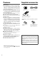
Features Supplied accessories Amplifier Features Check that the following accessories are supplied with this unit. ■ 55 Watts MINIMUM OF CONTINUOUS RMS POWER to each of the five channels into 8 ohms from 20 Hz to 20 kHz with no more than 0.08% THD (North American models, FTC rating) — enough solid, clean power to drive your home theater speakers with authority and produce dynamically rich music, even at low volume levels.
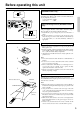
Before operating this unit Setting the AM tuning step frequency (Worldwide models only) 10kHz 9kHz Worldwide models are equipped with a switch that controls the AM band tuning steps. Please set this switch to match the AM band tuning step frequency in your area. U.S.A.
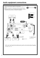
Audio equipment connections • On each pair of input jacks, a red connector (marked R) corresponds to the right • • • channel, and a white connector (marked L) to the left channel. Please refer to the instruction manual of each component when making any connections. This receiver is designed for use with turntables using moving magnet cartridges. Insert the plugs and connectors securely. Remember that improper connection can result in noise, poor performance, or damage to the equipment.
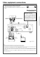
Video equipment connections • On each pair of input jacks, a red connector (marked R) corresponds to the right • • channel, and a white connector (marked L) to the left channel. A yellow connector (marked V) is used for video connection. Please refer to the instruction manual of each component when making any connections.
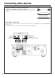
Connecting other devices • On each pair of input jacks, a red connector (marked R) corresponds to the right • • Audio connection cable channel, and a white connector (marked L) to the left channel. A yellow connector (marked V) is used for video connection. Please refer to the instruction manual of each component when making any connections. L (Left) L R (Right) R Video connection cable V (Video) V Monaural audio cable (mono) decoder with 5.1 channel output You may connect the 5.
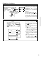
Connecting other devices AC outlet connection SUB WOOFER PRE OUT ANTENNA AM R L MULT I CHANNEL I NPUT L R DIGITAL INPUT DIGITAL 2 (COAXIAL) FRONT CENTER SPEAKER (REC) OUT TAPE DIGITAL 1 (OPTICAL) SURROUND MONITOR OUT (PLAY) IN L L R R SURROUND SPEAKERS FM 75 DVD IN OUT L AC OUTLETS AC 120V 60Hz SWITCHED TOTAL 120W 1A MAX. FRONT SPEAKERS A B IN GND REMOTE CONTROL SUB CENTER WOOFER VIDEO-1 L L R R MODEL NO. TX-DS474 VIDEO-2 IN R R PHONO L V CD U.S.A.
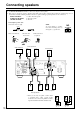
Connecting speakers • If you want to use the surround effects, connect surround speakers. For the best results, connect a center speaker. • Use FRONT SPEAKERS B terminals to connect a second pair of front speakers. • This receiver is designed to produce optimum sound quality when speakers with impedances within the specified ranges are connected. Please check the following information and choose speakers with appropriate impedances for the connections. FRONT SPEAKERS: A or B: 6 ohms min.
Positioning speakers Positioning speakers Speaker placement plays an important role in the reproduction of Surround sound. The placement of the speakers varies depending on the size of the room and the wall coverings used in the room. The illustration shows an example of a layout for standard speaker placement. Refer to this example when you position the speakers in order to experience the best of Surround sound.
Making antenna connections Connecting the antenna cable to the 75/300 ohm antenna adapter (Worldwide models) Outdoor antenna Indoor antenna 300 ohms ribbon wire 1 2 3 ✦ ✦ ✦ ✦ ✦ ✦ ✦✦ ✦ ✦ ✦ 6 3 6 mm mm mm Slit B 15mm Connecting the 300 ohm ribbon wire: Loosen the screws and wrap the wire around these screws. Then tighten the screws with a screwdriver. Connecting the coaxial cable: 1. With your fingernail or a small screwdriver, press the stoppers outward and remove the cover. 2.
Making antenna connections Connecting the included antennas ANTENNA AM Connecting the T-shaped FM antenna: The T-shaped FM antenna is for indoor use only. Extend the antenna and move it in various directions until the clearest signal is received. Fix it with push pins or similar implements in the position that will cause the least amount of distortion. If the reception is not very clear with the attached T-shaped FM antenna, the use of an outdoor antenna is recommended.
Speaker setup PARAMETER SELECTOR/ PARAMETER CONTROLLER buttons Use these buttons to set the speaker parameters, such as the type and distance.
Speaker setup 6 PARAMETER SELECTOR PARAMETER CONTROLLER PARAMETER SELECTOR 7 PARAMETER CONTROLLER 8 PARAMETER SELECTOR PARAMETER CONTROLLER 9, 10 PARAMETER SELECTOR dB or dB PARAMETER CONTROLLER 11 PARAMETER SELECTOR PARAMETER CONTROLLER 1, 3 6. Press the PARAMETER SELECTOR® button to display the front speaker position parameter, and press the PARAMETER CONTROLLER √/® button repeatedly to set the distance value from your listening position to the front speaker.
Selecting a sound source Follow the steps below to select a device to play the sound source. 2. Make sure that the SPEAKERS A indicator is lit on the display. If it is not lit, press the SPEAKERS A button. (Refer to the “Speakers selector” section on the page 18 for more details.) DIMMER button Use this button to change the brightness of the display (normal or dim). 4. Adjust the volume to an appropriate level.
Selecting a sound source When Multi channel input is selected as a source 1 POWER SLEEP DIMMER SUR MODE GROUP CD Follow the steps below to adjust the level of each speaker if you have selected MULTI-CH INPUT. MULTI-CH INPUT INPUT SELECTOR TAPE TUNER PHONO DVD VIDEO-1 VIDEO-2 CD TUNER PRESET DVD MULTI-CH INPUT DISC TAPE CH SEL LEVEL 1. Press MULTI-CH INPUT button on the remote controller. You cannot select any Surround mode. 2. Press the CH SEL button to select the desired speakers. 3.
Selecting a sound source Speakers selector (SPEAKERS A, B) SPEAKERS A: This button turns on or off the speakers connected to the FRONT SPEAKERS A, CENTER SPEAKER, SURROUND SPEAKERS and SUBWOOFER terminals. When you select Dolby Pro Logic, Hall, Live, or Multi-CH INPUT, be sure to turn on SPEAKERS A. When the speakers are turned on, the SPEAKERS A indicator lights up. SPEAKERS B: This button turns on or off the speakers connected to the FRONT SPEAKERS B terminals.
Selecting a sound source Sleep function (Remote controller only) The sleep timer can turn off the power to the system after a specified time period. To set up this function, use the remote controller supplied with this receiver. 1. Start playing the source you would like to listen to (CD, tape, or radio broadcast). 2. Press the SLEEP button repeatedly to set the duration of time after which you want the system to turn off. The longest timer value you can set is 90 minutes.
To enjoy Surround mode or Stereo mode 2. SURROUND MODE button This button allows you to select a Surround mode. MIDNIGHT THEATER button Use this button to play sound in Dolby Digital mode (refer to page 21). VOLUME knob Use this knob to adjust the volume level.
To enjoy Surround mode or Stereo mode Selecting a Surround mode SURROUND MODE Dolby Pro Logic / Dolby Digital Stereo / Dolby Digital (Stereo) Live Hall Arena 1. Press an Input Selector button to select the desired sound source. 2. Press the SURROUND MODE button repeatedly until the desired Surround mode name appears. The display changes in the order shown on left each time you press the button. • If you are using the remote controller, press the SUR MODE button to select the desired Surround mode.
Tuning in a radio station √ TUNING ® MASTER VOLUME STANDBY/ON PARAMETER SELECTOR STANDBY PARAMETER CONTROLLER POWER SCAN PRESET GROUP TUNING HIGH CURRENT DISCRETE OUTPUT STAGE AMPLIFIER ON OFF A SPEAKERS B SURROUND MODE MIDNIGHT THEATER MEMORY FM MUTE / MODE DIMMER CLEAR PHONES MULTI CH INPUT DVD VIDEO 1 VIDEO 2 TAPE(MONITOR) FM AM PHONO BASS TREBLE CD AUDIO VIDEO CONTROL RECEIVER TX-DS474 FM AM FM MUTE/MODE Manual tuning 1 FM AM SPEAKERS A 1. Press the FM or AM button.
Using preset radio stations SCAN GROUP AM FM √ TUNING ® POWER SLEEP DIMMER SUR MODE MULTI-CH INPUT INPUT SELECTOR TAPE TUNER PHONO DVD CD MASTER VOLUME STANDBY/ON GROUP PARAMETER SELECTOR VIDEO-1 VIDEO-2 GROUP CD TUNER PRESET DVD TUNER √ PRESET ® STANDBY PARAMETER CONTROLLER POWER SCAN PRESET GROUP DISC TUNING HIGH CURRENT DISCRETE OUTPUT STAGE AMPLIFIER ON OFF A SPEAKERS B SURROUND MODE MIDNIGHT THEATER MEMORY FM MUTE / MODE DIMMER TAPE CLEAR MULTI CH INPUT PHONES VIDEO
Recording a source 1 Recording an audio source 2 MASTER VOLUME STANDBY/ON PARAMETER SELECTOR STANDBY PARAMETER CONTROLLER POWER SCAN PRESET GROUP TUNING HIGH CURRENT DISCRETE OUTPUT STAGE AMPLIFIER ON OFF A SPEAKERS B SURROUND MODE MIDNIGHT THEATER MEMORY FM MUTE / MODE DIMMER CLEAR MULTI CH INPUT PHONES VIDEO 1 DVD VIDEO 2 TAPE(MONITOR) FM AM PHONO BASS TREBLE CD AUDIO VIDEO CONTROL RECEIVER TX-DS474 1·3 3 Turntable CD player Tape deck (TAPE) VCR, VDP DVD 2 VIDEO 1 DVD
Recording a source Recording data from a video disc player (or a video camcorder) to VCR 1 MASTER VOLUME STANDBY/ON PARAMETER SELECTOR Video disc programs can be recorded onto a VCR (VIDEO-2). STANDBY PARAMETER CONTROLLER POWER SCAN PRESET GROUP TUNING HIGH CURRENT DISCRETE OUTPUT STAGE AMPLIFIER ON OFF A SPEAKERS B SURROUND MODE MIDNIGHT THEATER CLEAR MULTI CH INPUT PHONES VIDEO 1 DVD VIDEO 2 TAPE(MONITOR) 1.
Troubleshooting guide If a problem occurs while you are using the remote controller, first try to operate the front panel controls on the main unit to make sure that it is not due to a malfunction (or worn out batteries) in the remote controller. Trouble Cause No power. • • Power on but no sound. • • • • • No sound from the center speaker, or very minimal sound. • • • • • • • Hum, low-frequency noise. Howling when the volume is turned up. Rough or scratchy sound. High range is not clear.
Specifications AMPLIFIER SECTION Continuous Average Power output (FTC) All channels: 55 watts per channel min. RMS at 8 ohms, 2 channels driven from 20 Hz to 20 kHz with no more than 0.08% total harmonic distortion. 70 watts min. RMS at 6 ohms, 2 channels driven from 1 kHz with no more than 0.1% total harmonic distortion. Continuous Power output (DIN) 75 watts × 5 at 6 ohms Maximum Power output (EIAJ) 100 watts × 5 at 6 ohms Total Harmonic Distortion: 0.08% at rated power (Front) IM Distortion: 0.
Control positions and names 1 2 3 6 4 5 7 8 10 9 MASTER VOLUME STANDBY/ON PARAMETER SELECTOR STANDBY PARAMETER CONTROLLER POWER SCAN PRESET GROUP TUNING HIGH CURRENT DISCRETE OUTPUT STAGE AMPLIFIER ON OFF A SPEAKERS B SURROUND MODE MIDNIGHT THEATER MEMORY FM MUTE / MODE DIMMER CLEAR MULTI CH INPUT PHONES VIDEO 1 DVD TAPE(MONITOR) VIDEO 2 FM AM BASS TREBLE CD PHONO AUDIO VIDEO CONTROL RECEIVER 17 18 a Display 16 b LIVE DOLBY PRO LOGIC HALL DOLBY DIGITAL ARENA STERE
Remote controller RC-385S 7 8 POWER 1 2 3 SLEEP DIMMER SUR MODE MULTI-CH INPUT 9 INPUT SELECTOR TAPE TUNER PHONO DVD VIDEO-1 VIDEO-2 GROUP CD CD TUNER PRESET 10 DVD DISC 11 4 TAPE CH SEL 12 TEST TONE 13 5 LEVEL MUTING VOLUME 1. Power button (POWER) [11] 2. Sleep button (SLEEP) [16, 19] 3. Input selector buttons [16] (Video 1, 2, PHONO, CD, DVD, TAPE) 4. CD operation buttons [30] 5. Tape operation buttons [30] 6. Level up/down button (LEVEL π/†) [14, 15, 17] 7.
Using the remote controller Listening to the radio POWER 1 2 SLEEP SUR MODE DIMMER MULTI-CH INPUT INPUT SELECTOR TAPE TUNER PHONO DVD VIDEO-1 VIDEO-2 TUNER PRESET GROUP CD CD 3 DVD 1. Press the TUNER button. 2. Press the GROUP button to select the desired GROUP. 3. Use the PRESET buttons to select the desired station.
MEMO 31
Sales & Product Planning Div. : 2-1, Nisshin-cho, Neyagawa-shi, OSAKA 572-8540, JAPAN Tel: 0720-31-8111 Fax: 0720-33-5222 ONKYO U.S.A. CORPORATION 200 Williams Drive, Ramesy, N.J. 07446, U.S.A. Tel: 201-825-7950 Fax: 201-825-8150 E-mail: onkyo@onkyousa.com ONKYO EUROPE ELECTRONICS GmbH Industriestrasse 20, 82110 Germering, GERMANY Tel: 089 84 93 20 Fax: 089 84 93 226 E-mail: info@onkyo.