Contents Stereo Receiver Introduction .................................... 2 TX-8555 Instruction Manual Connections ................................. 13 Enjoying Audio Sources.............. 22 Others Troubleshooting .............................. 45 Specifications .................................. 47 Thank you for purchasing an Onkyo Stereo Receiver. Please read this manual thoroughly before making connections and plugging in the unit.
WARNING: TO REDUCE THE RISK OF FIRE OR ELECTRIC SHOCK, DO NOT EXPOSE THIS APPARATUS TO RAIN OR MOISTURE. CAUTION: TO REDUCE THE RISK OF ELECTRIC SHOCK, DO NOT REMOVE COVER (OR BACK). NO USER-SERVICEABLE PARTS INSIDE. REFER SERVICING TO QUALIFIED SERVICE PERSONNEL.
Precautions 1. Recording Copyright—Unless it’s for personal use only, recording copyrighted material is illegal without the permission of the copyright holder. 2. AC Fuse—The AC fuse inside the unit is not userserviceable. If you cannot turn on the unit, contact your Onkyo dealer. 3. Care—Occasionally you should dust the unit all over with a soft cloth. For stubborn stains, use a soft cloth dampened with a weak solution of mild detergent and water. Dry the unit immediately afterwards with a clean cloth.
Precautions—Continued For British models Replacement and mounting of an AC plug on the power supply cord of this unit should be performed only by qualified service personnel.
Table of Contents Introduction Enjoying Audio Sources Important Safety Instructions.................................2 Precautions ..............................................................3 Table of Contents ....................................................5 Supplied Accessories .............................................6 Turning On the Receiver .......................................22 Installing the Batteries .................................................6 Remote Controller .............
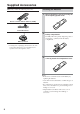
Supplied Accessories Make sure you have the following accessories: Installing the Batteries 1 Detach the battery cover by pressing the tab and pulling up the cover. 2 Insert two AA-size batteries into the battery compartment. Carefully follow the polarity diagram (positive + and negative - symbols) inside the battery compartment. 3 After batteries are installed and seated correctly, attach the compartment cover.
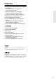
Features ❑ Newly Designed, Brushed Hairline Aluminum Front Panel ❑ 100 Watts/Channel @ 8 ohms (FTC) (North American model) ❑ 125 Watts/Channel @ 4 ohms (IEC) (European and Australian model) ❑ WRAT (Wide Range Amplifier Technology) ❑ High-Current, Low-Impedance Drive ❑ Discrete Output Stage Circuitry ❑ XM and SIRIUS Ready (North American model) ❑ 6 Audio Inputs (CD, TAPE, GAME/TV, CBL/SAT, DVD, VCR/DVR) ❑ 4 Video Inputs (GAME/TV, CBL/SAT, DVD, VCR/DVR) ❑ Phono Input ❑ 2 Audio and Video Outputs ❑ Speaker A/B
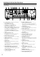
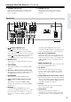
Getting to Know the Receiver Front Panel 1 2 3 4 567 8 V 9 U For detailed information, see the pages in parentheses. A ON/STANDBY button (22) Sets the receiver to On or Standby. B SPEAKERS A and B switches (23) Turn speaker sets A and B on or off. C ZONE 2 LEVEL, TONE, [▲] / [▼] buttons (38) The LEVEL button and [▲]/[▼] buttons are used when adjusting the volume level of Zone 2. The TONE button and [▲]/[▼] buttons are used when adjusting the Bass/Treble level and balance of Zone 2.
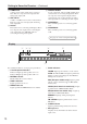
Getting to Know the Receiver—Continued U STANDBY indicator (22) V PHONES jack (24) Lights up when the receiver is on Standby and flashes while a signal is being received from the remote controller. This 1/4-inch phone jack is for connecting a standard pair of stereo headphones for private listening. Rear Panel 1 B 3 4 5 67 KL M N OP Q A 8 9 R J S REMOTE CONTROL jack This (Remote Interactive) jack can be connected to the jacks on your other Onkyo audio components.
Getting to Know the Receiver—Continued N GAME/TV IN Q VCR/DVR IN/OUT A game console or TV output can be connected here. There are composite video input jack and analog audio input jacks. A video component, such as a VCR or DVR, can be connected here for recording and playback. There are composite video input and output jacks for connecting the video signal, and there are analog audio input jacks for connecting the audio signal. O CBL/SAT IN A cable or satellite receiver can be connected here.
Remote Controller To control the AV receiver, press the [RECEIVER] Remote Mode button to select Receiver mode. You can also use the remote controller to control your DVD player, CD player, and other components. See pages 40-43 for more details. For detailed information, see the pages in parentheses. 1 2 A ON/STANDBY button (22) Sets the receiver to On or Standby. B ZONE 2 button (37) Used when setting Zone 2. C INPUT SELECTOR buttons (23) and number buttons (29) Selects the input sources. After the D.
Remote Controller—Continued S RETURN button Selects the previously displayed setup menu. T PURE A button (25) Selects the Pure Audio listening mode. Note: • An Onkyo cassette recorder connected via can also be controlled in Receiver mode (see page “Controlling a Cassette Recorder” on page 43). Using the Remote Controller Point the remote controller toward the remote control sensor.
Connecting Your Speakers Disconnect the power cord from the wall outlet before making any connections. Speaker Connection Precautions Connecting the Speaker Cables The receiver allows you to connect two sets of speakers. When two sets of speakers are connected, you can select which speaker set outputs sound or use both sets to output sound simultaneously.
Connecting Your Speakers—Continued Connecting a Powered Subwoofer Using a suitable cable, connect the receiver’s PRE OUT: SUBWOOFER to the input on your powered subwoofer. If your subwoofer is unpowered and you’re using an external amplifier, connect the PRE OUT: SUBWOOFER to the amp’s input.
Connecting Your Speakers—Continued Configuring the Speaker Impedance In this model, the factory default for speaker impedance is “8 ohms.” When you change the speaker impedance setting, read “Speaker Connection Precautions” on page 13 carefully before performing the procedures below. Note: Be sure to minimize the volume level on the receiver before configuring the speaker impedance. 3 Use the Up and Down [▲]/[▼] buttons to select “1. Hardware set,” and then press [ENTER].
Connecting Antenna This section explains how to connect the supplied indoor FM antenna and AM loop antenna, and how to connect commercially available outdoor FM and AM antennas. The receiver won’t pick up any radio signals without any antenna connected, so you must connect the antenna to use the tuner. Connecting the AM Loop Antenna The supplied indoor AM loop antenna is for indoor use only. 1 Assemble the AM loop antenna, inserting the tabs into the base, as shown.
Connecting Antenna—Continued Connecting an Outdoor FM Antenna Connecting an Outdoor AM Antenna If you cannot achieve good reception with the supplied indoor FM antenna, try a commercially available outdoor FM antenna instead. If good reception cannot be achieved using the supplied AM loop antenna, an outdoor AM antenna can be used in addition to the loop antenna, as shown.
Connecting Your Components Before Making any Connections Connecting a Turntable • Always refer to the instructions that came with the component that you are connecting. • Do not plug in the power cord until all connections have been properly made. • Do not bind audio cables with power cords and speaker cables. Doing so may adversely affect the sound quality. • To prevent interference, keep power cords and speaker cables away from the tuner’s antenna.
Connecting Your Components—Continued Connecting a Recording Component To connect recording components, such as cassette deck, MD recorder and CD recorder, use an analog audio cable to connect the receiver’s TAPE IN L/R jacks to the cassette deck’s analog audio output jacks, and use another analog audio cable to connect the receiver’s TAPE OUT L/R jacks to the cassette deck’s analog audio input jacks, as shown.
Connecting Your Components—Continued Connecting a VCR Use an analog audio cable to connect the VCR/DVR IN L/R jacks to the analog audio output jacks on the VCR, and use a video cable to connect the VCR/DVR IN V jack to the composite video output jack on the VCR. Then use an analog audio cable to connect the VCR/DVR OUT L/R jacks to the analog audio input jacks on the VCR, and use a video cable to connect the VCR/DVR OUT V jack to the composite video input jack on the VCR.
Connecting Your Components—Continued With (Remote Interactive), you can control your -compatible Onkyo CD player, RI Dock, and so on with the receiver’s remote controller. • To use , you must make an analog audio connection between the receiver and each audio component. Receiver Connecting the Power Cords of Other Components The receiver has AC outlets on its rear panel that can be used to connect the power cords of other components that you intend to use with the receiver.
Turning On the Receiver ON/STANDBY ON/STANDBY STANDBY indicator Turning On and Standby 1 Receiver or Press the [ON/STANDBY] button. Alternatively, press the remote controller’s [ON/STANDBY] button. The receiver comes on, the display lights up, and the STANDBY indicator goes off. Remote controller To turn the receiver off, press the [ON/STANDBY] button, or press the remote controller’s [ON/STANDBY] button. The receiver will enter Standby mode.
Enjoying Audio Sources Input selector buttons SPEAKERS A/B INPUT SELECTOR MASTER VOLUME VOLUME / SP A/B 1 Receiver Press the input selector button to select the component that you want to listen to. Receiver Receiver Remote controller Remote controller 2 4 To adjust the volume, use the receiver’s [MASTER VOLUME] control, or the remote controller’s VOLUME [ ]/[ ] buttons. Turn the control clockwise to turn up the volume or counterclockwise to turn down the volume.
Enjoying Audio Sources—Continued DIMMER SLEEP MUTING PHONES Muting the receiver (remote controller only) You can temporarily mute the output of the receiver. 1 Press the remote controller’s [MUTING] button. The receiver is muted. To unmute the receiver, press the [MUTING] button again. Note: The Mute function will be cancelled if the remote controller’s VOLUME buttons are pressed or the receiver is set to Standby.
Enjoying Audio Sources—Continued This section explains functions that can be used with any input source. PURE AUDIO TREBLE BASS BALANCE Using the Tone and Balance Controls Adjusting the Bass The BASS control adjusts bass sounds. Turn it up to make them louder. Turn it down to make them quieter. Normally, it should be set midway. Adjusting the Treble The TREBLE control adjusts treble sounds. Turn it up to make them louder. Turn it down to make them quieter. Normally, it should be set midway.
Recording Unless you have the full consent of the copyright holder, copyright laws prohibit using your recordings for anything other than personal enjoyment! This section explains how to record the selected input source to a component with recording capability. Input selector buttons Recording the Input Source You can record an audio signal on a recording component connected to the TAPE OUT, or VCR/DVR OUT jacks. 1 Prepare the recorder: • Set the recorder so that it’s ready for recording.
Recording—Continued Recording Audio and Video from Separate Sources You can overdub audio onto your video recordings by simultaneously recording audio and video from two separate sources. This is possible because only the audio source is switched when an audio-only input source, such as TAPE, TUNER, or CD, is selected, the video source remains the same.
Listening to the Radio TUNING DOWN/UP DIRECT TUNING Number buttons Number buttons D.TUN CLR TUNING / / TUNER TUNING MODE AM Frequency Step Setup (not North America and Europe) 2 Receiver You must specify the AM frequency step used in your area. Note that when this setting is changed, all radio presets are deleted. Use the receiver to perform the procedure below. 1 and While pressing the [TUNER] button, press the [TUNING MODE] button.
Listening to the Radio—Continued ■ Tuning into Stations by Frequency You can tune into AM and FM stations directly by entering the appropriate frequency. 1 Receiver Remote controller 4 Receiver Press the [DIRECT TUNING] button. (Actual display depends on country.) ■ Selecting Presets 1 2 Receiver Press the [MEMORY] button again to store the station or channel. The station or channel is stored and the preset number stops flashing. Repeat this procedure for all of your favorite AM/FM radio stations.
Listening to the Radio—Continued Using RDS (European Model Only) RDS only works with European models and only in areas where RDS broadcasts are available. When tuned into an RDS station, the RDS indicator appears. RDS indicator Type Display None NONE News reports NEWS Current affairs AFFAIRS Information INFO Sport SPORT Education EDUCATE Drama DRAMA ■ What is RDS? RDS stands for Radio Data System and is a method of transmitting data in FM radio signals.
Listening to the Radio—Continued Displaying Radio Text (RT) DISPLAY 4 To start the search, press [ENTER]. The receiver searches until it finds a station of the type you specified, at which point it stops briefly before continuing with the search. 5 When a station you want to listen to is found, press [ENTER]. If no stations are found, the message “Not Found” appears. When tuned to an RDS station that’s broadcasting text information, the text can be displayed. 1 Press the [DISPLAY] button once.
Naming Preset Channels While receiving a preset FM or AM station, a maximum of 8 characters consisting of letters, numbers and some symbols can be stored, for example to represent the station name. You cannot assign a name to the RDS station (for European model) and the XM/SIRIUS Radio channel (for North American model). The input display name can be changed in the same sequence as described below. (Note that changing the input display name does not change the input source.
Advanced Setup Setting the Advanced Setup 3 Use the Up and Down [ ]/[ ] buttons to select “1. Hardware set,” and then press [ENTER]. The Hardware setup menu appears in the display. 4 Use the Up and Down [ ]/[ ] buttons to select “Remote ID: 1” indication. 5 Change the Remote ID to “3” using the Left and Right [ ]/[ buttons. 6 Press the SETUP button on the remote controller to complete the setting. When you change the Advanced Setup setting, perform the procedures below.
Advanced Setup—Continued Advanced Setup Menu 1.Hardware set Remote ID When several Onkyo components are used in the same room, their remote ID codes may overlap. To differentiate the receiver from the other components, you can change its remote ID from 1, the default, to 2 or 3. Note: • If you do change the receiver’s remote ID, be sure to change the remote controller to the same ID, otherwise, you won’t be able to control it with the remote controller. Impedance See page 15. Z2 Out See page 36. 2.
Zone 2 In addition to your main listening room, you can also enjoy playback in the other room, or as we call Zone 2. And, you can select a different source for each room. Connecting Zone 2 This setup allows 2-channel playback (with the speaker set A and B) in your main listening room and 2-channel stereo playback in Zone 2, with a different source in each room. Hookup • Use an RCA audio cable to connect the receiver’s ZONE 2 PRE OUT L/R jacks to an analog audio input on your Zone 2 amp.
Zone 2—Continued Zone 2 Out Settings 3 Use the Up and Down [ ]/[ ] buttons to select “Z2 Out: Fixed.” 4 Use the Left and Right [ ]/[ ] buttons to select: Fixed: The Zone 2 volume must be set on the amp in that zone. Variable: The Zone 2 volume can be set on the receiver. 5 Press the [SETUP] button. Setup closes.
Zone 2—Continued Using Zone 2 This section explains how to turn Zone 2 on and off, how to select an input source for Zone 2, and how to adjust the volume for Zone 2. Controlling Zone 2 from the receiver ZONE 2 LEVEL/TONE Notes: • While Zone 2 is on, the Auto Power On/Standby and Direct Change functions do not work. • When you control Zone 2 with the remote controller while main room is standby, the display doesn’t work.
Zone 2—Continued 3 To turn off Zone 2, press the [ZONE 2] button, followed by the [ON/STANDBY] button. 3 Use the Up and Down [ ]/[ ] buttons to adjust the balance. You can adjust the balance from 0 in the center to +12 dB to the right or +12 dB to the left in 2 dB steps. Muting Zone 2 On the remote controller, press the [ZONE 2] Remote Mode button, and then press the [MUTING] button. Note: • To control Zone 2, you must press the remote controller’s [ZONE 2] button first.
Connecting Components not Reached by the Remote Controller Signals (IR IN/OUT) In order to use the remote controller to control the receiver from a remote location, you will need to prepare a multiroom kit (sold separately) such as one listed below: • Multiroom A/V distribution and control system such as those from Niles® and Xantech® * Xantech is a registered trademark of Xantech Corporation. * Niles is a registered trademark of Niles Audio Corporation.
Controlling Other Components Controlling an Onkyo DVD Player The [DVD] Remote Mode button is preprogrammed with the remote control code for controlling an Onkyo DVD player. Press the appropriate Remote Mode button first. A ON/STANDBY button Sets the DVD player to On or Standby. B Number buttons Used to enter title, chapter, and track numbers, and to enter times for locating specific points. The [+10] button works as a +10 button or “-.--” button.
Controlling Other Components—Continued Controlling an Onkyo CD Player The [CD] Remote Mode button is preprogrammed with the remote control code for controlling an Onkyo CD player. Press the appropriate Remote Mode button first. A ON/STANDBY button Set the component to On or Standby. B Number buttons Used to enter track numbers and times for locating specific points. The [+10] button works as a +10 button or “-.--” button. C TOP MENU button Displays a menu.
Controlling Other Components—Continued A ON/STANDBY button Controlling an RI Dock Turns the iPod on or off. By pressing the Remote Mode button that has been programmed with the remote control code for your RI Dock, you can control your iPod in the RI Dock with the following buttons. The [DOCK] Remote Mode button is preprogrammed with the remote control code for controlling an Onkyo RI Dock. When Using an RI Dock: • Connect the RI Dock to the TAPE IN or VCR/DVR IN L/R jacks.
Controlling Other Components—Continued P Previous [ ] button Restarts the current song. Press it twice to select the previous song. Q REPEAT button* On twin cassette decks, only Deck B can be controlled. A ON/STANDBY button Turns the cassette recorder on or off. B Reverse Play [ ] button Used with the repeat function. Starts reverse playback. R RANDOM button* C Rewind and Fast Forward [ Used with the shuffle function.
Controlling Other Components—Continued Programming a remote control code for controlling components connected via By default, the [DVD], [CD], and [DOCK] REMOTE MODE buttons have been programmed with the remote control codes for controlling Onkyo products. To control the components connected via , follow the steps below to program the appropriate remote control code for the component to be used. 1 Resetting the REMOTE MODE Buttons You can reset a REMOTE MODE button to its default remote control code.
Troubleshooting If you have any trouble using the receiver, look for a solution in this section. If you can’t resolve the issue yourself, try resetting the receiver before contacting your Onkyo dealer. To reset the receiver to its factory defaults, turn it on and, while holding down the [VCR/DVR] button, press the [ON/STANDBY] button. Note that resetting the receiver will delete your radio presets and custom settings.
Troubleshooting—Continued Remote Controller The remote controller doesn’t work • Make sure that the batteries are installed with the correct polarity (page 6). • Install new batteries. Don’t mix different types of batteries or old and new batteries (page 6). • Make sure that the remote controller is not too far away from the receiver, and that there’s no obstruction between the remote controller and the receiver’s remote control sensor (page 12).
Specifications Amplifier Section General Rated Output Power (FTC) (North American) All channels: 100 watts minimum continuous power per channel, 8 ohm loads, 2 channels driven from 20 Hz to 20 kHz, with a maximum total harmonic distortion of 0.
Sales & Product Planning Div. : 2-1, Nisshin-cho, Neyagawa-shi, OSAKA 572-8540, JAPAN Tel: 072-831-8023 Fax: 072-831-8163 ONKYO U.S.A. CORPORATION 18 Park Way, Upper Saddle River, N.J. 07458, U.S.A. Tel: 201-785-2600 Fax: 201-785-2650 http://www.us.onkyo.com/ ONKYO EUROPE ELECTRONICS GmbH Liegnitzerstrasse 6, 82194 Groebenzell, GERMANY Tel: +49-8142-4401-0 Fax: +49-8142-4401-555 http://www.eu.onkyo.