Contents Introduction ...................................2 AV Controller Connection ..................................18 PR-SC5507 Turning On & First Time Setup .....43 Basic Operations.........................62 Instruction Manual Using the Listening Modes ........75 Advanced Setup ..........................86 NET/USB ...................................115 Multi Zone ................................125 Thank you for purchasing an Onkyo AV Controller.
WARNING: TO REDUCE THE RISK OF FIRE OR ELECTRIC SHOCK, DO NOT EXPOSE THIS APPARATUS TO RAIN OR MOISTURE. CAUTION: TO REDUCE THE RISK OF ELECTRIC SHOCK, DO NOT REMOVE COVER (OR BACK). NO USER-SERVICEABLE PARTS INSIDE. REFER SERVICING TO QUALIFIED SERVICE PERSONNEL.
Precautions 1. Recording Copyright—Unless it’s for personal use only, recording copyrighted material is illegal without the permission of the copyright holder. 2. AC Fuse—The AC fuse inside the unit is not userserviceable. If you cannot turn on the unit, contact your Onkyo dealer. 3. Care—Occasionally you should dust the unit all over with a soft cloth. For stubborn stains, use a soft cloth dampened with a weak solution of mild detergent and water. Dry the unit immediately afterwards with a clean cloth.
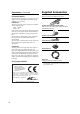
Precautions—Continued Supplied Accessories For British models Make sure you have the following accessories: Replacement and mounting of an AC plug on the power supply cord of this unit should be performed only by qualified service personnel.
Contents Introduction Important Safety Instructions ............................................ 2 Precautions....................................................................... 3 Supplied Accessories ....................................................... 4 Features............................................................................ 6 Front & Rear Panels ......................................................... 8 Front Panel ...................................................................
Features Processing Miscellaneous *1 • THX Ultra2 Plus Certified • HQV-Reon-VX Video Processing with 1080p Video Upscaling of All Video Sources via HDMI • HDMI ver.1.3a with (Deep Color, x.v.
Features—Continued *8. Manufactured under license from Audyssey Laboratories. U.S. and foreign patents pending. Audyssey MultEQ® XT, Audyssey Dynamic Surround Expansion™, Audyssey Dynamic Volume™ and Audyssey Dynamic EQ™ are trademarks of Audyssey Laboratories. This product incorporates copyright protection technology that is protected by U.S. patents and other intellectual property rights.
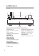
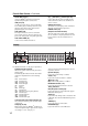
Front & Rear Panels Front Panel Pull here to open the flap Front flap The actual front panel has various logos printed on it. They are not shown here for clarity. The page numbers in parentheses show where you can find the main explanation for each item. ON/STANDBY button (43) This button is used to set the AV controller to On or Standby. STANDBY indicator (43) Lights when the AV controller is in Standby mode, and it flashes while a signal is being received from the remote controller.
Front & Rear Panels—Continued (North American models) (European and Asian models) The page numbers in parentheses show where you can find the main explanation for each item. PHONES jack (64) This 1/4-inch phone jack is for connecting a standard pair of stereo headphones for private listening. ZONE 2, ZONE 3, and OFF buttons (129) The [ZONE 2] button is used to select Zone 2. The [ZONE 3] button is used to select Zone 3. The [OFF] button is used to turn off Zone 2 or Zone 3.
Front & Rear Panels—Continued SETUP MIC jack (57) Audyssey MultEQ® XT Room Correction and Speaker Setup microphone connects here. USB port (122) A USB mass storage device, such as a USB flash drive or MP3 player, containing music files can be plugged in here and the music selected can be played through the AV controller. AUX1 INPUT (38) This input can be used to connect a camcorder, game console, and so on. There are jacks for composite video, analog audio, and optical digital audio.
Front & Rear Panels—Continued SLEEP indicator (64) Lights when the Sleep function has been set. Bi AMP indicator (21) Lights when the “Speakers Type(Front)” setting is set to “Bi-Amp”. Headphone indicator (64) Lights when a pair of headphones are plugged into the PHONES jack. Message area Displays various information. USB indicator (123) Lights up when a USB mass storage device is detected. Volume level (62) Displays the volume level. MUTING indicator (64) Flashes while the AV controller is muted.
Front & Rear Panels—Continued REMOTE CONTROL This (Remote Interactive) jack can be connected to an jack on another Onkyo AV component. The AV controller’s remote controller can then be used to control that component. To use , you must make an analog audio connection (RCA) between the AV controller and the other AV component, even if they are connected digitally. RS232 Terminal for control. GND screw This screw is for connecting a turntable’s ground wire.
Front & Rear Panels—Continued PRE OUT: FRONT L/R, CENTER, SURR L/R, SURR BACK L/R, and FRONT HIGH/WIDE L/R These multichannel analog audio outputs can be connected to the analog audio input on a multichannel power amplifier. PRE OUT: SW1, SW2 These analog audio outputs can be connected to a powered subwoofer. You can connect the powered subwoofer with each jacks respectively. Level and distance can be set individually for each output.
Remote Controller Installing the Batteries 1 To open the battery compartment, press the small lever and remove the cover. Aiming the Remote Controller To use the remote controller, point it at the AV controller’s remote control sensor, as shown below. Transmission Remote control sensor AV controller 2 Insert the two supplied batteries (AA/R6) in accordance with the polarity diagram inside the battery compartment. Approx. 16 ft.
Remote Controller—Continued Controlling the AV Controller To control the AV controller, press the [RECEIVER] button to select Receiver mode. You can also use the remote controller to control your DVD/BD player, CD player, and other components. See pages 133 to 147 for more details. For detailed information, see the pages in parentheses. STANDBY button (43) Sets the AV controller to Standby. ON button (43) Turns on the AV controller. ACTIVITIES buttons (65, 147) Used with the MACRO function.
Remote Controller—Continued ■ Controlling the tuner To control the AV controller’s tuner, press the [TUNER] (or [RECEIVER]) button. You can select AM or FM by pressing the [TUNER] button repeatedly. 1 Arrow [ ]/[ ] buttons Used to tune into radio stations. 2 D.TUN button (67) (TUNER remote mode only) Selects the Direct tuning mode. 3 DISPLAY button Displays information about the band, frequency, preset number, and so on. 4 CH +/– button (68) Used to select radio presets.
About Home Theater Enjoying Home Theater Thanks to the AV controller’s superb capabilities, you can enjoy surround sound with a real sense of movement in your own home—just like being in a movie theater or concert hall. With DVDs you can enjoy DTS and Dolby Digital. With analog or digital TV, you can enjoy Dolby Pro Logic IIx, DTS Neo:6, or Onkyo’s original DSP listening modes. You can also enjoy THX Surround EX (THX-certified THX speaker system recommended).
Connecting the AV controller Connecting Your Speakers The AV controller is designed to be used with a separate multichannel power amplifier. You connect the AV controller’s PRE OUT jacks to the amplifier’s inputs, and connect your speakers to the amplifier’s speakers terminals. Speaker settings such as crossover frequency and distance are set on the AV controller. Speaker Configuration For 9.2-channel surround-sound playback, you need nine speakers and two powered subwoofers.
Connecting the AV controller—Continued Using Dipole Speakers Normal speakers Dipole speakers You can use dipole speakers for the surround left and right, surround back left and right speakers. Dipole speakers output the same sound in two directions. Dipole speakers typically have an arrow printed on them to indicate how they should be positioned.
Connecting the AV controller—Continued Connecting a Power Amplifier with XLR Inputs You can connect the AV controller to a multichannel power amplifier with balanced XLR input jacks by using several XLR audio cables. The AV controller’s balanced PRE OUT XLR jacks are wired as shown. See your multichannel power amplifier’s instruction manual for more information on connecting speakers.
Connecting the AV controller—Continued Bi-amping the Front Speakers The FRONT L/R and SURR BACK L/R outputs can be used with front speakers and surround back speakers, respectively, or bi-amped to provide separate tweeter and woofer feeds for a pair of front speakers that support bi-amping, providing improved bass and treble performance. • When bi-amping is used, the AV controller is able to feed up to 7.2 speakers in the main room.
Connecting the AV controller—Continued Connecting Antenna This section explains how to connect the supplied indoor FM antenna and AM loop antenna, and how to connect commercially available outdoor FM and AM antennas. The AV controller won’t pick up any radio signals without any antenna connected, so you must connect the antenna to use the tuner. AM ANTENNA push terminals FM ANTENNA jack Connecting the Indoor FM Antenna The supplied indoor FM antenna is for indoor use only.
Connecting the AV controller—Continued Connecting an Outdoor FM Antenna Connecting an Outdoor AM Antenna If you cannot achieve good reception with the supplied indoor FM antenna, try a commercially available outdoor FM antenna instead. If good reception cannot be achieved using the supplied AM loop antenna, an outdoor AM antenna can be used in addition to the loop antenna, as shown.
Connecting the AV controller—Continued AV Connection Color Coding About AV Connections • Before making any AV connections, read the manuals supplied with your other AV components. • Don’t connect the power cord until you’ve completed and double-checked all AV connections. Optical Digital Jacks The AV controller’s optical digital jacks have shuttertype covers that open when an optical plug is inserted and close when it’s removed. Push plugs in all the way.
Connecting the AV controller—Continued Audio OPTICAL Optical digital audio cable Coaxial digital audio cable Balanced XLR cable Analog audio cable (RCA) Multichannel analog audio cable (RCA) L R Offers the best sound quality and allows you to enjoy surround sound (e.g., Dolby Digital, DTS). The audio quality is the same as for coaxial. Offers the best sound quality and allows you to enjoy surround sound (e.g., Dolby Digital, DTS). The audio quality is the same as for optical.
Connecting the AV controller—Continued Supported Audio Formats • 2-channel linear PCM (32–192 kHz, 16/20/24 bit) • Multichannel linear PCM (up to 7.1 ch, 32–192 kHz, 16/20/24 bit) • Bitstream (DSD, Dolby Digital, Dolby Digital Plus, Dolby TrueHD, DTS, DTS Express, DTS-HD High Resolution Audio, DTS-HD Master Audio) Your DVD/BD players must also support HDMI output of the above audio formats.
Connecting the AV controller—Continued Making HDMI Connections Step 1: Use HDMI cables to connect the AV controller’s HDMI jacks to your HDMI-compatible DVD/BD player, TV, projector, and so on. Step 2: Assign each HDMI IN to an input selector in the HDMI Input Setup (see page 49). ■ Video Signals Digital video signals received by the HDMI IN jacks are normally output by the HDMI MAIN OUT and SUB OUT for display on your TV.
Connecting the AV controller—Continued Connecting Both Audio & Video By connecting both the audio and video outputs of your DVD/BD player and other AV components to the AV controller, you can select both the audio and video simultaneously simply by selecting the appropriate input source on the AV controller. : Signal Flow Video Video Audio Audio TV, projector, etc. DVD/BD player, etc. On Power On Of f Standby Seven Channel Amplifier RDA-7.
Connecting the AV controller—Continued ■ “Monitor Out” Setting Set to “Both”, “Both(Main)” or “Both(Sub)” DVD/BD player, etc. Video Signal Flow Chart With the “Monitor Out” setting set to “Both”, “Both(Main)” or “Both(Sub)” (see page 47), video input signals flow through the AV controller as shown, with composite video, S-Video, and Composite S-Video Component HDMI component video sources all being upconverted IN for both HDMI outputs.
Connecting the AV controller—Continued Audio Connection Formats Audio equipment can be connected to the AV controller by using any of the following audio connection formats: analog, optical, coaxial, analog multichannel, or HDMI. When choosing a connection format, bear in mind that the AV controller does not convert digital input signals for analog line outputs and vice versa. For example, audio signals connected to an optical or coaxial digital input are not output by the analog TV/TAPE OUT.
Connecting the AV controller—Continued Connecting a TV or Projector See “Connecting Components with HDMI” on page 25 for HDMI connection information. Step 1: Video Connection Choose a video connection that matches your TV ( A , B , or C ), and then make the connection. Step 2: Audio Connection Choose an audio connection that matches your TV ( a , b , or c ), and then make the connection. • With connection a , you can listen to and record audio from your TV or listen in Zone 2 or Zone 3.
Connecting the AV controller—Continued Connecting a DVD Player See “Connecting Components with HDMI” on page 25 for HDMI connection information. Step 1: Video Connection Choose a video connection that matches your DVD player ( A , B , or C ), and then make the connection. You must connect the AV controller to your TV via the same type of connection. Step 2: Audio Connection Choose an audio connection that matches your DVD player ( a , b , or c ), and then make the connection.
Connecting the AV controller—Continued Hooking Up the Multichannel Input If your DVD player supports multichannel audio formats such as DVD-Audio and Super Audio CD, and it has a multichannel analog audio output, you can connect it to the AV controller’s multichannel input. Use a multichannel analog audio cable, or several normal audio cables, to connect the AV controller’s MULTI CH: FRONT L/R, CENTER, SURR L/R, SURR BACK L/R, and SUBWOOFER jacks to the 7.1-channel analog audio output on your DVD player.
Connecting the AV controller—Continued Connecting a VCR or DVD Recorder for Playback Hint! With this hookup, you can use your VCR’s tuner to listen to your favorite TV programs via the AV controller, useful if your TV has no audio outputs. Step 1: Video Connection Choose a video connection that matches your VCR or DVD recorder ( A , B , or C ), and then make the connection. You must connect the AV controller to your TV via the same type of connection.
Connecting the AV controller—Continued Connecting a VCR or DVD Recorder for Recording Step 1: Video Connection Choose a video connection that matches your VCR or DVD recorder ( A or B ), and then make the connection. The video source to be recorded must be connected to the AV controller via the same type of connection. Step 2: Audio Connection Make the audio connection a .
Connecting the AV controller—Continued Connecting a Satellite, Cable, Terrestrial Set-top box, or Other Video Source Hint! With this hookup, you can use your satellite or cable receiver to listen to your favorite TV programs via the AV controller, useful if your TV has no audio outputs. Step 1: Video Connection Choose a video connection that matches the video source ( A , B , or C ), and then make the connection. You must connect the AV controller to your TV via the same type of connection.
Connecting the AV controller—Continued Connecting a Game Console Step 1: Video Connection Choose a video connection that matches your game console ( A , B , or C ), and then make the connection. You must connect the AV controller to your TV with the same type of connection. Step 2: Audio Connection Choose an audio connection that matches your game console ( a or b ), and then make the connection. • With connection a , you can listen to and record audio from your game console or listen in Zone 2 or Zone 3.
Connecting the AV controller—Continued Connecting a Camcorder or Other Device Step 1: Video Connection Make the connection A . Step 2: Audio Connection Choose an audio connection that matches your camcorder ( a or b ), and then make the connection. Connection AV controller Signal flow Camcorder etc.
Connecting the AV controller—Continued Connecting a CD Player or Turntable ■ CD Player or Turntable (MM) with Built-in Phono Preamp Step 1: Choose a connection that matches your CD player ( a , b , or c ). Use connection a for a turntable with a built-in phono preamp. • With connection a , you can listen to and record audio from your CD player or listen in Zone 2 or Zone 3. • To connect the CD player digitally, use connection b or c .
Connecting the AV controller—Continued Connecting a Cassette, CDR, MiniDisc, or DAT Recorder Step 1: Choose a connection that matches the recorder ( a , b or c ), and then make the connection. • With connection a , you can play and record or listen in Zone 2 or Zone 3. • To connect the recorder digitally for playback, use connections a and b , or a and c .
Connecting the AV controller—Continued Connecting an RI Dock Not all iPod models output video. For information about which iPod models are supported by the RI Dock, see the RI Dock’s instruction manual. ■ If Your iPod Supports Video: Connect your RI Dock’s audio output jacks to the AV controller’s GAME IN or VCR/DVR IN L/R jacks, and connect its video output jack to the AV controller’s GAME IN V or VCR/DVR IN V jack. (Onkyo DS-A2 hookup shown below.
Connecting the AV controller—Continued Connecting Onkyo Components IN L Step 1: Make sure that each Onkyo component is connected to the AV controller with an analog audio cable (connection a in the hookup examples) (see pages 31 to 40, 41). Step 2: Make the CD REMOTE CONTROL IN L R DVD/BD connection (see illustration right). Step 3: If you’re using an MD, CDR, or RI Dock, change the Input Display (see page 55).
Turning On the AV controller (European and Asian models) (North American models) STANDBY ON/STANDBY STANDBY indicator ON/STANDBY STANDBY indicator ON RECEIVER POWER Turning On and Standby 1 (European and Asian models) 2 On the AV controller, press the [ON/STANDBY] button. Set the [POWER] switch to the ON position ( ). AV controller Remote controller or On the remote controller, press the [RECEIVER] button, followed by the [ON] button.
First Time Setup This section explains the settings that you need to make before using the AV controller for the very first time. ■ Change “Monitor Out” setting manually Monitor Setup If you connect your TV to HDMI OUT MAIN, “Monitor Out” setting is automatically set so that the onscreen setup menus are displayed and composite video, SVideo, and component video sources are upconverted* and output.
First Time Setup—Continued In this Instruction Manual, illustrations from the onscreen menu or explanations referring to the menu will be in the same language as the Instruction Manual. The default Language setting for the onscreen menu is English. If your Instruction Manual is in a language other than English, first follow the instructions below to change the Language. Selecting the Language used for the onscreen setup menus 3 This setting determines the language used for the onscreen setup menus.
First Time Setup—Continued Using the Display to change the settings The settings of the AV controller can be changed using the Display. RECEIVER 1 Press the [RECEIVER] button followed by the [SETUP] button. The main menu item appears on the display. 2 Use the Up and Down [ ]/[ ] buttons to select item and then press [ENTER]. The submenu item appears on the display. Press the [SETUP] button to close the menu. Press the [RETURN] button to return to the previous menu.
First Time Setup—Continued 4 Monitor Out Setup If you connect your TV to the HDMI output, set the “Monitor Out” setting so that the onscreen setup menus are displayed and composite video, S-Video, and component video sources are upconverted and output. If you connect your TV to the COMPONENT VIDEO MONITOR OUT, set the “Monitor Out” setting so that the onscreen setup menus are displayed and composite video and S-Video sources are upconverted and output.
First Time Setup—Continued 5 Use the Up and Down [ ]/[ ] buttons to select “Resolution”, and use the Left and Right [ ]/[ ] buttons to select: Through: Select this to pass video through the AV controller at the same resolution and with no conversion. Auto * : Select this to have the AV controller automatically convert video at resolutions not supported by your TV. 480p (480p/576p): Select this for 480p or 576p output and video conversion as necessary.
First Time Setup—Continued Video Input Setup 4 Use the Up and Down [ ]/[ ] buttons to select an input selector, and use the Left and Right [ ]/ [ ] buttons to select: HDMI1, HDMI2, HDMI3, HDMI4, HDMI5, HDMI6, HDMI7: Select the HDMI IN to which the video component has been connected. - - - - -: Output composite video, S-Video, and component video sources from the HDMI outputs. The video output signal from the HDMI outputs is the one configured in “Component Video Input Setup” (see page 50).
First Time Setup—Continued Component Video Input Setup If you connect to a COMPONENT VIDEO IN or PC INPUT ANALOG RGB, you must assign it to an input selector. For example, if you connect your DVD/BD player to COMPONENT VIDEO IN 2, you should assign it to the DVD/BD input selector. If you’ve connected your TV to the AV controller with a component video cable, you can set the AV controller so that composite video and S-Video sources are upconverted* and output by the COMPONENT VIDEO MONITOR OUT*1.
First Time Setup—Continued Digital Audio Input Setup 4 Use the Up and Down [ ]/[ ] buttons to select an input selector, and use the Left and Right [ ]/ [ ] buttons to select “COAX1”, “COAX2”, “COAX3”, “OPT1”, “OPT2”, “OPT3”, or “- - - - - (analog)”. • When an HDMI IN is assigned to an input selector in “HDMI Input Setup” on page 49, the AV controller will select audio from HDMI IN as a priority. • Press the [ENTER] button when you do not use the signal of audio from the HDMI IN.
First Time Setup—Continued Analog Audio Input Setup If you connect a component to the AV controller’s analog multichannel input, you must assign that input to an input selector. For example, if you connect your DVD/ BD player to the multichannel input, you must assign it to the DVD/BD input selector. If you connect a component to the AV controller’s balanced input, you must assign that input to an input selector.
First Time Setup—Continued Speaker Settings 4 Use the Up and Down [ ]/[ ] buttons to select “Speakers Type(Front)”, and then use the Left and Right [ ]/[ ] buttons to select: Normal: Select this if you’ve connected your front speakers normally. Bi-Amp: Select this if you’ve connected your front speakers for bi-amped operation. Note: Surround back speakers cannot be used if you select “Bi-Amp”. 5 Press the [SETUP] button. The setup menu closes.
First Time Setup—Continued TV Format Setup (European and Asian models) 5 For the onscreen setup menus to display properly, you must specify the TV system used in your area. 1 2 Press the [RECEIVER] button followed by the [SETUP] button. The main menu appears onscreen. If the main menu doesn’t appear, make sure the appropriate external input is selected on your TV. Use the Up and Down [ ]/[ ] buttons to select “6. Miscellaneous”, and then press [ENTER]. The “Miscellaneous” menu appears.
First Time Setup—Continued 3 GAME Use the Up and Down [ ]/[ ] buttons to select “3. Tuner”, and then press [ENTER]. The “Tuner” menu appears. TV/TAPE (North American models) 7–3. Tuner FM/AM Frequency Step SAT Radio Mode 200kHz/10kHz None VCR/DVR (European and Asian models) 1 7–3. Tuner AM Frequency Step 4 Press the [TV/TAPE], [GAME] or [VCR/DVR] input selector button so that “TV/TAPE”, “GAME” or “VCR/DVR” appears on the display.
First Time Setup—Continued Audyssey MultEQ® XT Room Correction and Speaker Setup With the supplied calibrated microphone, Audyssey MultEQ XT automatically determines the number of speakers connected, their size for purposes of bass management, optimum crossover frequencies to the subwoofer (if present), and distances from the primary listening position.
First Time Setup—Continued Using Audyssey MultEQ® XT 1 Turn on the AV controller and the connected TV. On the TV, select the input to which the AV controller is connected. 2 Set the speaker setup microphone at the Main Listening Position (page 56), and connect it to the SETUP MIC jack. The speaker setting menu appears.
First Time Setup—Continued • Make the room as quiet as possible. Background noise can disrupt the room measurements. Close windows, silence cell phones, televisions, radios, air conditioners, fluorescent lights, home appliances, light dimmers, or other devices. • Cell phones should be turned off or placed away from all audio electronics during the measurement process as Radio Frequency Interference (RFI) may cause measurement disruptions (even if the cell phone is not in use).
First Time Setup—Continued 9 When the calculations are complete, the following screen appears. MultEQ XT: Auto Setup -- Review SP Configuration -Subwoofer No Front Full Band Center 40Hz Surround 120Hz Front Wide None Front High None Surr Back 150Hz Surr Back Ch 2ch Save Cancel Use the Up and Down [ ]/[ ] buttons to select an option, and then press [ENTER]. The options are: Save: Save the calculated settings and exit the room correction and speaker setup.
First Time Setup—Continued MultEQ XT: Auto Setup MultEQ XT: Auto Setup Speaker Detect Error FL SL FWL FHL SBL C : : : : : : Yes --No Yes --Yes FR SR FWR FHR SBR SW1 SW2 Speaker Detect Error : : : : : : : FL SL FWL FHL SBL C No --No Yes ------- Retry Cancel : : : : : : Yes --No Yes --Yes FR SR FWR FHR SBR SW1 SW2 : : : : : : : Yes No No Yes ------- Retry Cancel One of the front speakers has not been detected. The front high speakers have been detected but the surround speakers haven’t.
First Time Setup—Continued Changing the Speaker Settings Manually MultEQ XT: Auto Setup Speaker Detect Error FL SL FWL FHL SBL C : Error : Yes : --: --: Yes : Yes FR SR FWR FHR SBR SW1 SW2 : : : : : : : Yes Yes ----Yes Yes Yes Retry Cancel The speaker type detected does not match what was expected. The speaker may be incorrect type or broken. Please check that it is the correct speaker type.
Basic Operations Selecting the Input Source This section explains how to select the input source (i.e., the AV component that you want to listen to or watch). MASTER VOLUME INPUT SELECTOR RECEIVER VOL / Input selector buttons 1 AV controller Remote controller Use the AV controller’s input selector buttons to select the input source. To select the input source with the remote controller, press the [RECEIVER] button, and then press the INPUT SELECTOR buttons.
Basic Operations—Continued Notes: • This setting is not available when the multichannel Analog input is selected. • To bypass the bass and treble tone circuits, select the Direct, Pure Audio or THX listening mode. DISPLAY Displaying Source Information You can display various information about the current input source as follows. TONE, , DIMMER Remote controller DISPLAY Press [RECEIVER] first.
Basic Operations—Continued Setting the Display Brightness You can adjust the brightness of the AV controller’s display. Remote controller Press the [RECEIVER] button, and then press the [DIMMER] button repeatedly to select: • Normal + VOLUME light on. • Normal + VOLUME light off. • Dim + VOLUME light off. • Dimmer + VOLUME light off. Alternatively, you can use the AV controller’s [DIMMER] button (North American models). Muting the AV Controller You can temporarily mute the output of the AV controller.
Basic Operations—Continued Using Easy Macros MY MUSIC (default): 1. The Onkyo CD player connected to the AV controller is turned on. 2. The AV controller is turned on. 3. The input selector of the AV controller is set to “CD”. 4. The player starts playback. Note: Once you start the Easy macro command, you cannot use other ACTIVITIES buttons during the execution. If you want to operate other components halfway, press the [ALL OFF] to stop and press desired ACTIVITIES button.
Basic Operations—Continued Changing Source Component When you want to operate the component that is not assigned as the source component, you can assign it as the source component. For the default assignment, see page 145. (3 seconds) While holding down the REMOTE MODE button, press and hold down the [MY MOVIE], [MY TV], or [MY MUSIC] button (about 3 seconds). The ACTIVITIES buttons that you pressed flashes twice, indicating that the setting has been established.
Listening to the Radio Using the Tuner TUNED AUTO With the built-in tuner you can enjoy AM and FM radio stations. You can store your favorite stations as presets for quick selection. FM STEREO TUNER ■ Manual Tuning Mode TUNING MODE TUNING / 1 Press the [TUNING MODE] button so that the AUTO indicator disappears from the display. 2 Press and hold the TUNING Up or Down [ ]/[ ] buttons. The frequency stops changing when you release the button.
Listening to the Radio—Continued Presetting AM/FM Stations MEMORY PRESET AV controller / To select a preset, use the PRESET [ ]/[ ] buttons, or the remote controller’s CH [+/–] button. or Remote controller You can store a combination of up to 40 of your favorite AM/FM radio stations as presets. or 1 Tune into the AM/FM station that you want to store as a preset. 2 Press the [MEMORY] button. The preset number flashes.
Listening to the Radio—Continued Using RDS (European models) RDS only works in areas where RDS broadcasts are available. When tuned into an RDS station, the RDS indicator appears. RDS indicator ■ What is RDS? RDS stands for Radio Data System and is a method of transmitting data in FM radio signals. It was developed by the European Broadcasting Union (EBU) and is available in most European countries. Many FM stations use it these days.
Listening to the Radio—Continued When tuned to an RDS station that’s broadcasting text information, the text can be displayed. Displaying Radio Text (RT) 3 To start the search, press [ENTER]. The AV controller searches until it finds a station of the type you specified, at which point it stops briefly before continuing with the search. 4 When a station you want to listen to is found, press [ENTER]. If no stations are found, the message “Not Found” appears. RT/PTY/TP Press the [RT/PTY/TP] button once.
Universal Port Option UP-A1 Dock for iPod About the UP-A1 Dock With the UP-A1 Dock (sold separately), you can easily play the music, photo, or movie stored on your Apple iPod through the AV controller and enjoy great sound. You can use the AV controller’s remote controller to operate your iPod. For the latest information on the Dock, see the Onkyo Web site at: http://www.onkyo.
Universal Port Option UP-A1 Dock for iPod—Continued Arrow [ ]/[ ] and ENTER buttons Used to navigate menus and select items. Controlling iPod By pressing the REMOTE MODE button that’s been programmed with the remote control code for your Dock, you can control your iPod in the Dock with the following buttons. The [PORT] button is preprogrammed with the remote control code for controlling a Dock with Universal Port connector. For details on entering a remote control code, see page 135.
Universal Port Option UP-A1 Dock for iPod—Continued Status messages ❏ PORT Reading The AV controller is checking the connection with the dock. ❏ PORT Not Support The AV controller do not support the connected dock. ❏ PORT UP-A1 UP-A1 Dock is connected. Notes: • The AV controller displays the message “UP-A1” for several seconds after recognizing the UP-A1. • When the status message is not displayed on the AV controller’s display, check the connection to your iPod.
Recording This section explains how to record the selected input source to a component with recording capability, and how to record audio and video from different sources. Notes: • The surround sound and DSP listening modes cannot be recorded. • Copy-protected DVDs cannot be recorded. • Sources connected to a digital input cannot be recorded. Only analog inputs can be recorded. • DTS signals will be recorded as noise, so don’t attempt analog recording of DTS CDs or LDs.
Using the Listening Modes Selecting Listening Modes Selecting with the Remote Controller See “About the Listening Modes” on page 83 for detailed information about the listening modes. • The Dolby Digital and DTS listening modes can only be selected if your DVD player is connected to the AV controller with a digital audio connection (coaxial, optical, or HDMI). • The listening modes you can select depend on the format of the input signal. To check the format, see “Displaying Source Information” on page 63.
Using the Listening Modes—Continued Listening Modes Available for Each Source Format The Speaker layout illustration shows which speakers are set to active in the “Speaker Configuration” setting (see page 90).
Using the Listening Modes—Continued Stereo Source (1/2) ✔: Available Listening Modes Speaker layout LH LW Listening Mode Button FL RH C FR SW LH RW LW SW SL SBR RH C FR SW SR SBL FL LH RW LW SW SL SBR RH C FR SW SR SBL FL LH RW LW SW SL SBR RH C SL SR SBL SBR ✔ ✔ ✔ Direct ✔ ✔ ✔ ✔ Stereo ✔ ✔ ✔ ✔ Mono ✔ ✔ ✔ ✔ ✔ ✔ ✔ ✔ ✔ ✔ ✔ ✔ ✔ PLII/PLIIx Movie*1 PLII/PLIIx Music*1 PLII/PLIIx Game*1 RW SW ✔ Pure Audio*3 FR SW SR SBL FL ✔ PLIIz Height
Using the Listening Modes—Continued Stereo Source (2/2) ✔: Available Listening Modes Speaker layout LH LW Listening Mode Button FL RH C FR SW LH RW LW SW SL SBR RH C FR SW SR SBL FL LH RW LW SW SL SBR RH C FR SW SR SBL FL LH RW LW SW SL SBL SBR ✔ RH C RW SW SL SR SBL SBR ✔ ✔ ✔ ✔ ✔ ✔ ✔ Orchestra ✔ ✔ Unplugged ✔ ✔ Studio-Mix ✔ ✔ TV Logic ✔ ✔ Game-RPG ✔ ✔ Game-Action ✔ ✔ Game-Rock ✔ ✔ Game-Sports ✔ ✔ All Ch Stereo ✔ ✔ ✔ Full Mono ✔ ✔ ✔
Using the Listening Modes—Continued 5.
Using the Listening Modes—Continued 5.
Using the Listening Modes—Continued 5.1 channel Sources (3/3) ✔: Available Listening Modes Speaker layout LH LW Listening Mode Button FL RH C FR SW RW LW SW SL SBR FL RH C FR SW SR SBL T-D (TheaterDimensional) DTS Surround Sensation LH LH RW LW SW SL SBR RH C FR SW SR SBL FL LH RW LW SW SL SBR RH C FR SW SR SBL FL RW SW SL SR SBL SBR ✔ ✔ ✔ ✔ ✔ ✔ ✔ ✔ Notes: *1 AV controller can input the DSD signal from HDMI IN.
Using the Listening Modes—Continued 7.
Using the Listening Modes—Continued Notes: *1 Based on the audio channels contained in the source, the corresponding speakers will output the sound. *2 This listening mode can be selected only when all the following conditions are satisfied: a. Center speaker is connected to the power amplifier. b. Either of Front High speakers or Front Wide speakers is connected to the power amplifier. *3 This listening mode is not available while you are using Zone 2 (“Not Available” will appear on the display).
Using the Listening Modes—Continued 5.1-channel source + Dolby EX These modes expand 5.1-channel sources for 6.1/7.1channel playback. They’re especially suited to Dolby EX soundtracks that include a matrix-encoded surround back channel. The additional channel adds an extra dimension and provides an enveloping surround sound experience, perfect for rotating and fly-by sound effects.
Using the Listening Modes—Continued THX Founded by George Lucas, THX develops stringent standards that ensure movies are reproduced in movie theaters and home theaters just as the director intended. THX Modes carefully optimize the tonal and spatial characteristics of the soundtrack for reproduction in the home-theater environment. They can be used with 2channel matrixed and multichannel sources. Surround back speaker output depends on the source material and the selected listening mode.
Advanced Setup Onscreen Setup Menus The onscreen setup menus appear on the connected TV and provide a convenient way to change the AV controller’s various settings. Settings are organized into nine categories on the main menu, most containing a submenu. Main menu Submenus pages 87–88 1. Input/Output Assign Menu 1. 2. 3. 4. 5. 6. 1. Input/Output Assign 2. Speaker Setup 3. Audio Adjust 4. Source Setup 5. Listening Mode Preset 6. Miscellaneous 7. Hardware Setup 8. Remote Controller Setup 9.
Advanced Setup—Continued Input/Output Assign This section explains items on the “Input/Output Assign” menu. 1 2 3 Press the [RECEIVER] button followed by the [SETUP] button. The main menu appears onscreen. If the main menu doesn’t appear, make sure the appropriate external input is selected on your TV. Use the Up and Down [ ]/[ ] buttons to select “1. Input/Output Assign”, and then press [ENTER]. Use the Up and Down [ ]/[ ] buttons to select the submenu, and then press [ENTER].
Advanced Setup—Continued Component Video Input See “Component Video Input Setup” on page 50. Digital Audio Input See “Digital Audio Input Setup” on page 51. Analog Audio Input Multich See “Analog Audio Input Setup” on page 52. Subwoofer Input Sensitivity 0 dB (default), 5 dB, 10 dB, 15 dB Some DVD players output the LFE channel from their analog subwoofer output at 15 dB higher than normal. With this setting, you can change the AV controller’s subwoofer sensitivity to match your DVD player.
Advanced Setup—Continued Gamma Curve The color range and the brightness characteristic of a reproduced image depend on the TV or projector. With this setting, you can adjust the balance of the color signals (R, G, and B). To view the TV picture while setting, press the [ENTER] button. To return to the default, press the [CLR] button. The “Gamma Curve” setting is set respectively of HDMI main, HDMI sub, and analog.
Advanced Setup—Continued Speaker Setup Some of the settings in this section are set automatically by Audyssey MultEQ® XT Room Correction and Speaker Setup (see page 56). Here you can check the settings made by Audyssey MultEQ® XT Room Correction and Speaker Setup, or set them manually, which is useful if you change one of the connected speakers after using Audyssey MultEQ® XT Room Correction and Speaker Setup. Note: The Speaker Setup cannot be carried out while headphones are connected to the AV controller.
Advanced Setup—Continued LPF of LFE (Low-Pass Filter for the LFE Channel) 80Hz(THX) (default), 90Hz, 100Hz, 120Hz This setting is not set automatically by Audyssey MultEQ® XT Room Correction and Speaker Setup (see page 56). With this setting, you can specify the cutoff frequency of the LFE channel’s low-pass filter (LPF), which can be used to filter out unwanted hum. The LPF only applies to sources that use the LFE channel. * If you’re using THX-certified speakers, select “80Hz(THX)”.
Advanced Setup—Continued Level Calibration Level Calibration can be set automatically by Audyssey MultEQ® XT Room Correction and Speaker Setup (see page 56). If you prefer, you can adjust the level of each speaker with the built-in test tone so that the volume of each speaker is the same at the listening position.
Advanced Setup—Continued THX Audio Setup This setting is not set automatically by Audyssey MultEQ® XT Room Correction and Speaker Setup (see page 56). With the “SurrBack Sp Spacing” setting, you can specify the distance between your surround back speakers. If you’re using a THX-certified subwoofer, set the “THX Ultra2/Select2 Subwoofer” setting to “Yes”.
Advanced Setup—Continued Audio Adjust With the Audio Adjust functions and settings, you can adjust the sound and listening modes as you like. 1 2 3 Press the [RECEIVER] button followed by the [SETUP] button. The main menu appears onscreen. If the main menu doesn’t appear, make sure the appropriate external input is selected on your TV. Use the Up and Down [ ]/[ ] buttons to select “3. Audio Adjust”, and then press [ENTER]. Use the Up and Down [ ]/[ ] buttons to select the submenu, and then press [ENTER].
Advanced Setup—Continued Center Width 0 to 7 (default: 3) With this setting, you can adjust the width of the sound from the center speaker when using the Dolby Pro Logic IIx Music listening mode. Normally, if you’re using a center speaker, the center channel sound is output by only the center speaker. (If you’re not using a center speaker, the center channel sound will be distributed to the front left and right speakers to create a phantom center).
Advanced Setup—Continued Audyssey For “Dynamic EQ”, “Reference Level” and “Dynamic Volume”, you cannot change the settings before completing Audyssey MultEQ® XT Room Correction and Speaker Setup. Dynamic EQ Off: Audyssey Dynamic EQ™ off (default). On: Audyssey Dynamic EQ™ on. With Audyssey Dynamic EQ™, you can enjoy great sound even when listening at low volume levels.
Advanced Setup—Continued Theater-Dimensional Listening Angle Wide: Select if the listening angle is greater than 30 degrees (default). Narrow: Select if the listening angle is less than 30 degrees. With this setting, you can optimize the Theater-Dimensional listening mode by specifying the angle of the front left and right speakers relative to the listening position.
Advanced Setup—Continued Source Setup This section explains items on the “Source Setup” menu. Items can be set individually for each input selector. 1 Press the input selector buttons to select an input source. 4 Use the Up and Down [ ]/[ ] buttons to select an item, and then press [ENTER]. 2 Press the [RECEIVER] button followed by the [SETUP] button. The main menu appears onscreen. If the main menu doesn’t appear, make sure the appropriate external input is selected on your TV.
Advanced Setup—Continued Name Edit You can enter a custom name for each individual input selector (excluding TUNER) and radio preset for easy identification. When entered, the custom name will appear on the display. Notes: • To name a radio preset, use the [TUNER] button to select AM or FM, and then select the preset (see page 68). • (North American models) You cannot enter a custom name for SIRIUS radio presets.
Advanced Setup—Continued Zoom Mode This setting determines the aspect ratio.
Advanced Setup—Continued ISF Mode Custom: User setting (All items can be freely set.) Day: Setting when a room is bright. Night: Setting when a room is dark. The receiver has been designed to incorporate setup and calibration standards established by the Imaging Science Foundation (ISF).
Advanced Setup—Continued Resolution*2 Through: Select this to pass video through the AV controller at the same resolution and with no conversion (default). Auto: Select this to have the AV controller automatically convert video at resolutions not supported by your TV. When the “Monitor Out” is set to “Analog”, this setting will be changed to “Through”. 480p (480/576p): Select this for 480p or 576p output and video conversion as necessary. 720p: Select this for 720p output and video conversion as necessary.
Advanced Setup—Continued Red Brightness*2 –50 to +50 (default: 0) With this setting you can adjust the picture red brightness. “–50” is the darkest. “+50” is the brightest. Red Contrast*2 –50 to +50 (default: 0) With this setting you can adjust red contrast. “–50” is the least. “+50” is the greatest. Green Brightness*2 –50 to +50 (default: 0) With this setting you can adjust the picture green brightness. “–50” is the darkest. “+50” is the brightest.
Advanced Setup—Continued Assigning Listening Modes to Input Sources You can assign a default listening mode to each input source that will be selected automatically when you select each input source. For example, you can set the default listening mode to be used with Dolby Digital input signals. You can select other listening modes during playback, but the mode specified here will be resumed once the AV controller has been set to Standby. 1 Press the [RECEIVER] button followed by the [SETUP] button.
Advanced Setup—Continued Miscellaneous (Volume/OSD) Setup This section explains the items on the “Miscellaneous” menu. 1 2 Press the [RECEIVER] button followed by the [SETUP] button. The main menu appears onscreen. If the main menu doesn’t appear, make sure the appropriate external input is selected on your TV. Use the Up and Down [ ]/[ ] buttons to select “6. Miscellaneous”, and then press [ENTER]. The “Miscellaneous” menu appears. 6. Miscellaneous 1. 2. 3. 4. 5.
Advanced Setup—Continued OSD Setup Immediate Display On: Displayed (default). Off: Not displayed. This preference determines whether operation details are displayed onscreen when an AV controller function is adjusted. Even when “On” is selected, operation details may not be output if the input source is connected to an HDMI IN. Display Position Bottom: Bottom of the screen (default). Top: Top of the screen. This preference determines where on the screen operation details are displayed.
Advanced Setup—Continued Remote ID Remote ID 1, 2, 3 When several Onkyo components are used in the same room, their remote ID codes may overlap. To differentiate the AV controller from the other components, you can change its remote ID from 1, the default, to 2 or 3. Changing the Remote Controller’s ID 1 While holding down the [RECEIVER] button, press and hold down the [SETUP] button until the RECEIVER button lights up (about 3 seconds). 2 Use the number buttons to enter ID 1, 2, or 3.
Advanced Setup—Continued HDMI Audio TV Out Off: HDMI audio is not output to TV (default). On: HDMI audio is output to TV and the sound will be heard from the TV speakers. This preference determines whether audio received at the HDMI input is output from the HDMI outputs. You may want to turn this preference on if your TV is connected to the HDMI output and you want to listen to the audio from a component that’s connected to an HDMI input, through your TV’s speakers. Normally, this should be set to “Off”.
Advanced Setup—Continued HDMI Control (RIHD) This function allows controller. On: Off: enabled. disabled (default). -compatible components connected via HDMI to be controlled with the AV Notes: • , which stands for Remote Interactive over HDMI, is the name of the system control function found on Onkyo components. The AV controller can be used with CEC (Consumer Electronics Control), which allows system control over HDMI and is part of the HDMI standard.
Advanced Setup—Continued Network See “Network Settings” on page 121. Firmware Update Notes: • Perform the firmware update only when an announcement is posted on the Onkyo Web site. • It takes about 60 minutes to complete the firmware update. • When updating a firmware from a USB mass storage device, the AV controller searches the device which is connected earlier during power on. If two devices have been connected at the time of power on, the AV controller will search the device on the front panel.
Advanced Setup—Continued Lock Setup Digital Input Signal Formats With this preference, you can protect your settings by locking the setup menus. 1 Press the [RECEIVER] button followed by the [SETUP] button. The main menu appears onscreen. If the main menu doesn’t appear, make sure the appropriate external input is selected on your TV. 2 Use the Up and Down [ ]/[ ] buttons to select “9. Lock Setup”, and then press [ENTER]. The “Lock Setup” menu appears. 9.
Advanced Setup—Continued Using the Audio Settings You can change various audio settings by pressing the [AUDIO] button. 1 Press the [RECEIVER] button followed by the [AUDIO] button. The audio setting items appear on the display. 2 Use the Up and Down [ ]/[ ] buttons to select an item. 3 Use the Left and Right [ ]/[ ] buttons to change the setting. Repeat steps 2 and 3 for the other settings.
Advanced Setup—Continued Re-EQ Function With the Re-EQ function, you can compensate a soundtrack whose high-frequency content is too harsh, making it more suitable for home theater viewing. Re-EQ Off: Re-EQ Function off (default). On: Re-EQ Function on.
Advanced Setup—Continued Speaker Levels You can adjust the volume of each speaker while listening to an input source. These temporary adjustments are cancelled when the AV controller is set to Standby. To save the setting you made here, go to “Level Calibration” on page 92 before setting the AV controller to Standby. Subwoofer 1 –15.0 dB to +12.0 dB (default: 0.0 dB) Subwoofer 2 –15.0 dB to +12.0 dB (default: 0.0 dB) Center –12.0 dB to +12.0 dB (default: 0.
NET/USB About NET The AV controller is network-ready, which means you can hook it up to your home network with a standard Ethernet cable and enjoy the music files stored on your computer or media server. If your network is connected to the Internet, you can also enjoy Internet radio. Network Requirements ■ Ethernet Network The AV controller’s Ethernet port supports 10Base-T. For best results, a 100Base-TX switched Ethernet network is recommended.
NET/USB—Continued Listening to Internet Radio To receive Internet radio, you must connect the AV controller to a network with Internet access (page 115). You can select Internet radio stations by connecting to the AV controller from your computer and selecting stations in your Web browser. Preset up to 40 Internet radio stations. Internet radio URLs in the following formats are supported: PLS, M3U, and podcast (RSS).
NET/USB—Continued Playing Music Files on a Server 4 Use the Up and Down [ ]/[ ] buttons to select an item, and then press [ENTER]. A list of music files appears. This section explains how to play music files on a computer or media server through the AV controller. See pages 119 to 120 for details on supported music servers and music file formats. For Windows Media Player 11, see “Windows Media Player 11 Setup” on page 118. 1 Start your computer or media server.
NET/USB—Continued Random Playback The Random function can only be set while the PLAY screen is displayed. To play songs in random order, during playback (or while playback is paused or stopped), press the [RANDOM] button. All of the songs in the current folder will be played in random order. When all of the songs in the folder have been played once, they’ll all be played again in a different random order. To cancel random playback, press the [RANDOM] button again.
NET/USB—Continued Supported Audio File Formats For server playback, the AV controller supports the following music file formats: MP3, WMA, WAV, FLAC, Ogg Vorbis, AAC and LPCM. ■ MP3 • MP3 files must be MPEG-1/MPEG-2 Audio Layer 3 format with a sampling rate of 8 kHz, 11.025 kHz, 12 kHz, 16 kHz, 22.05 kHz, 24 kHz, 32 kHz, 44.1 kHz, 48 kHz and a bit-rate of between 8 kbps and 320 kbps. Incompatible files cannot be played. • Number of channels: 2 • Variable bit-rate (VBR) MP3 files are supported.
NET/USB—Continued Server Requirements The AV controller can play digital music files stored on a computer or media server and supports the following technologies: • Windows Media Player 11 • Windows Media Connect 2.0 • DLNA-certified media server If the operating system of your computer is Windows Vista, Windows Media Player 11 is already installed. Windows Media Player 11 for Windows XP can be downloaded for free from the Microsoft Web site.
NET/USB—Continued Network Settings 3 Note: When modifying network settings, after modifying it is necessary to execute “Save”. Use the Up and Down [ ]/[ ] buttons to select “5. Network”, and then press [ENTER]. The “Network” screen appears. 7-5. Network This section explains how to configure the AV controller’s network settings manually.
NET/USB—Continued Mac Address This is the AV controller’s MAC (Media Access Control) address. This address cannot be changed. DHCP This setting determines whether or not the AV controller uses DHCP to automatically configure its IP Address, Subnet Mask, Gateway, and DNS Server settings. Enable: DHCP enabled. Disable: DHCP disabled. If you select “Disable”, you must configure the “IP Address”, “Subnet Mask”, “Gateway”, and “DNS Server” settings yourself.
NET/USB—Continued Playing Music Files on a USB Device 3 Use the Up and Down [ ]/[ ] buttons to select a USB mass storage device, and then press [ENTER]. A list of the device’s contents appears. This section explains how to play music files on a USB mass storage device.
NET/USB—Continued Random Playback The Random function can only be set while the PLAY screen is displayed. To play songs in random order, while the list of songs is displayed, press the [RANDOM] button. All of the songs in the current folder will be played in random order. When all of the songs in the folder have been played once, they’ll all be played again in a different random order. To cancel random playback, press the [RANDOM] button again. Random playback supports up to 20,000 songs per folder.
Multi Zone Multiroom Capability You can use three speaker systems with this AV controller—a surround-sound speaker system (up to 9.2 channels) in your main listening room, Zone 2: a stereo speaker system in a second room, Zone 3: a stereo speaker system in a third room. And, you can select a different audio source for each room. Main room: Enjoy up to 9.2-channel surround-sound playback (see page 18). You can enjoy the various listening modes, such as Dolby, DTS, and THX (see pages 75 to 85).
Multi Zone—Continued In addition to your main listening room, you can also enjoy playback in the other room, or as we call Multi Zone. And, you can select a different source for each room. Connecting Zone 2 Zone 2 speakers must be connected to an amp in Zone 2. Connecting Your Zone 2 Speakers You can enjoy 2-channel stereo playback in Zone 2 and a different source to those selected for your main room and Zone 3.
Multi Zone—Continued Connecting Zone 3 Zone 3 speakers must be connected to an amp in Zone 3. Connecting Your Zone 3 Speakers You can enjoy 2-channel stereo playback in Zone 3 and a different source to those selected for your main room and Zone 2. Hookup • Use an RCA audio cable to connect the AV controller’s ZONE 3 PRE OUT L/R jacks to an analog audio input on your Zone 3 amp. • Use an RCA audio cable to connect the AV controller’s ZONE 3 PRE OUT SW jack to the line input on a powered subwoofer in Zone 3.
Multi Zone—Continued 5 Setting the Multi Zone 1 2 Press the [RECEIVER] button followed by the [SETUP] button. The main menu appears onscreen. If the main menu doesn’t appear, make sure the appropriate external input is selected on your TV. Use the Up and Down [ ]/[ ] buttons to select “7. Hardware Setup”, and then press [ENTER]. The “Hardware Setup” menu appears. 3 Remote ID Multi Zone Tuner HDMI Network Firmware Update Use the Up and Down [ ]/[ ] buttons to select “2.
Multi Zone—Continued Using Zone 2/3 Controlling Zone 2/3 with the Remote Controller This section explains how to turn Zone 2/3 on and off, how to select an input source for Zone 2/3, and how to adjust the volume for Zone 2/3. STANDBY ON ZONE Controlling Zone 2/3 from the AV controller ZONE 3 indicator ZONE 2 indicator INPUT SELECTOR Note: To control Zone 2/3, you must press the remote controller’s [ZONE] button first. The ZONE button turns red while Zone 2 is on, and green while Zone 3 is on.
Multi Zone—Continued Notes: • Only analog input sources are output by the ZONE 2 PRE OUT and ZONE 3 PRE OUT. Digital input sources are not output. If no sound is heard when an input source is selected, check if it’s connected to an analog input. • You cannot select different AM or FM radio stations for your main room and Zone 2/3. The same AM/FM radio station will be heard in each room. For example, if you have an FM station for the main room, that station will also be used in Zone 2.
Multi Zone—Continued Using the 12V Triggers 3 The 12V triggers A, B, and C can be used to turn on 12V trigger-capable components automatically when they are selected as the input source. The triggers can be set so that they activate when a connected component is selected as the input source for the main room, Zone 2, Zone 3, or any combination of rooms. When triggered, the output from a 12V TRIGGER OUT goes high (+12 volts and 150 milliamperes max. at TRIGGER OUT A; +12 volts and 25 milliamperes max.
Multi Zone—Continued Using the Remote Controller in Zone 2/3 and Multiroom Control Kits To control the AV controller with the remote controller while you’re in Zone 2 or Zone 3, you’ll need a commercially available multiroom remote control kit for each zone. • Multiroom kits are made by Niles and Xantech. These kits can also be used when there isn’t a clear line of sight to the AV controller’s remote sensor, such as when it’s installed inside a cabinet.
Controlling Other Components You can use the AV controller’s remote controller (RC-747M) to control your other AV components, including those made by other manufacturers. This section explains how to enter the remote control code for a component that you want to control: DVD, TV, VCR, etc. • Learn commands directly from another component’s remote controller (see page 146). • Program the ACTIVITIES buttons to perform a sequence of up to 32 remote control actions (see page 147).
Controlling Other Components—Continued 5 To use the remote controller, point it at the AV controller’s remote control sensor, as shown below. Use the Up and Down [ ]/[ ] buttons to select category, and then press [ENTER]. The brand name input panel appears. Transmitter AV controller 8–1. Remote Mode Setup TV Category Brand Incoming sensor TV 15 15 A N 1 6 B O 2 C P 3 D E Q R 4 5 Space F S 6 G T 7 H U 8 I J V W 9 0 Back Space K X – L M Y Z & @ Search Approx. 15° off center 16ft.
Controlling Other Components—Continued Entering Remote Control Codes 1 Look up the appropriate remote control code in the separate Remote Control Codes list. The codes are organized by category (e.g., DVD player, TV, etc.). 2 While holding down the REMOTE MODE button to which you want to enter a code, press and hold down the [DISPLAY] button (about 3 seconds). The REMOTE MODE button lights up. Notes: • Remote control codes cannot be entered for the [RECEIVER] and [ZONE] buttons.
Controlling Other Components—Continued Remote Control Codes for Onkyo Components Connected via Onkyo components that are connected via are controlled by pointing the remote controller at the AV controller, not the component. This allows you to control components that are out of view, in a rack, for example. 1 Make sure the Onkyo component is connected with an cable and an analog audio cable (RCA). See page 42 for details. 2 Enter the appropriate remote control code for the REMOTE MODE button.
Controlling Other Components—Continued Controlling a TV By pressing the [TV] button that’s been programmed with the remote control code for TV, you can control your TV with the following buttons. For details on entering a remote control code for a different component, see page 135. The [TV] button is preprogrammed with the remote control code for controlling a TV that supports the *1 (limited to some models).
Controlling Other Components—Continued Controlling a DVD Player or DVD Recorder By pressing the REMOTE MODE button that’s been programmed with the remote control code for your DVD player (HD DVD, Blu-ray, or TV/DVD combination), you can control your player with the following buttons. The [DVD/BD] button is preprogrammed with the remote control code for controlling an Onkyo DVD player. For details on entering a remote control code for a different component, see page 135.
Controlling Other Components—Continued PLAY MODE button* Selects play modes on components with selectable play modes. CLR button Cancels functions and clears entered numbers. Notes: • With some components, certain buttons may not work as expected, and some may not work at all. • If you enter the remote control code for a HD DVD or Blu-ray player that has A, B, C, and D or colored buttons, the [SEARCH], [REPEAT], [RANDOM], and [PLAY MODE] buttons will work as colored or A, B, C, D buttons.
Controlling Other Components—Continued Controlling a Satellite Receiver or Cable Receiver By pressing the REMOTE MODE button that’s been programmed with the remote control code for your satellite receiver, cable receiver, or DVD recorder (DBS/ PVR combination or cable/PVR combination), you can control your player with the following buttons. For details on entering a remote control code for a different component, see page 135. Press the appropriate REMOTE MODE button first.
Controlling Other Components—Continued Controlling a CD Player, CD Recorder or MD Recorder By pressing the REMOTE MODE button that’s been programmed with the remote control code for your CD player, CD recorder, or MD recorder, you can control your player with the following buttons. The [CD] button is preprogrammed with the remote control code for controlling an Onkyo CD player. For details on entering a remote control code for a different component, see page 135.
Controlling Other Components—Continued Controlling an RI Dock By pressing the REMOTE MODE button that’s been programmed with the remote control code for your Dock, you can control your iPod in the Dock with the following buttons. For some RI docks, the [ON], [STANDBY] button may not work with a remote control code 82990 (without ). In this case, make an connection and enter a remote control code 81993 (with ). For details on entering a remote control code, see page 135.
Controlling Other Components—Continued PLAY MODE button Selects play modes on components with selectable play modes. Works as a Resume button when used with a DS-A2 RI Dock. RANDOM button Used with the shuffle function. Note: With some components, certain buttons may not work as expected, and some may not work at all.
Controlling Other Components—Continued Activities Setup Via onscreen menu, you can specify what actions will be taken by the Easy macro command in the Easy macro mode. 1 2 Press the [RECEIVER] button followed by the [SETUP] button. The main menu appears onscreen. If the main menu doesn’t appear, make sure the appropriate external input is selected on your TV. Use the Up and Down [ ]/[ ] buttons to select “8. Remote Controller Setup”, and then press [ENTER]. The “Remote Controller Setup” menu appears. 8.
Controlling Other Components—Continued Source Play Enable: Start playback the source of “Enable”. Disable: Start playback the source of “Disable”. This option enables the Source to start playback when the ACTIVITIES button is pressed. 7 On the remote controller press the [ENTER] button. 8–2. Activities Setup My Movie Wait Here are the default settings.
Controlling Other Components—Continued Learning Commands If the command is learned successfully, the REMOTE MODE button flashes twice. C IS D H I-CT ULTPU M IN E R SUOD M D D C VID -1 EO ER C 4 REMOTE MODE While holding down the REMOTE MODE button for the mode in which you want to use the command, press and hold down the [ON] button until the REMOTE MODE button lights up (about 3 seconds).
Controlling Other Components—Continued Using Normal Macros 3 You can program the remote controller’s ACTIVITIES buttons to perform a sequence of remote control actions. Example: To play a CD you typically need to perform the following actions: 1. Press the [RECEIVER] button to select the Receiver remote controller mode. 2. Press the [ON] button to turn on the AV controller. 3. Press the [CD] button to select the CD input source. 4. Press the Play [ ] button to start playback on the CD player.
Troubleshooting If you have any trouble using the AV controller, look for a solution in this section. If you can’t resolve the issue yourself, contact your Onkyo dealer. If you can’t resolve the issue yourself, try resetting the AV controller before contacting your Onkyo dealer. To reset the AV controller to its factory defaults, turn it on and, while holding down the [VCR/DVR] button, press the [ON/STANDBY] button. “Clear” will appear on the display and the AV controller will enter Standby mode.
Troubleshooting—Continued The front high, front wide and surround back speakers produce no sound • Depending on the current listening mode, no sound may be produced by the front high, front wide, and surround back speakers. Select another listening mode (page 83). • Not much sound may be produced by the front high, front wide, and surround back speakers with some sources. • Make sure the speakers are configured correctly (page 90).
Troubleshooting—Continued Video There’s no picture • Make sure that all video connecting plugs are pushed in all the way (page 24). • Make sure that each video component is properly connected (pages 27 to 41). • If your TV is connected to the HDMI output, set the “Monitor Out” setting other than “Analog” (page 47), and select “- - - - -” in the “HDMI Input Setup” on page 49 to watch composite video, S-Video, and component video sources.
Troubleshooting—Continued • Make sure you’ve selected the correct remote controller mode (pages 15 and 137 to 143). • When using the remote controller to control other manufacturers’ AV components, some buttons may not work as expected. • Make sure you’ve entered the correct remote control code (page 135). • Make sure to set the same ID on both the AV controller and remote controller (page 107).
Troubleshooting—Continued Zone 2/3 There’s no sound • Only components connected to analog inputs can be played in Zone 2/3. Music Server and Internet Radio Can’t access the server or Internet radio • Check the network connection between the AV controller and your router or switch. • Make sure that your modem and router are properly connected, and make sure they are both turned on. • Make sure the server is up and running and compatible with the AV controller (page 120).
Troubleshooting—Continued The following settings can be made for the SVideo and composite video inputs You must use the buttons on the AV controller to make these settings. 1. While holding down the input selector button for the input source that you want to set, press the [SETUP] button. 2. Use the Left and Right [ ]/[ ] buttons to change the setting. 3. Press the input selector button for the input source that you want to set when you’ve finished.
Specifications Amplifier Section Input Sensitivity and Impedance 200 mV/47 kΩ (LINE) 2.5 mV/47 kΩ, (PHONO MM) Output Level and Impedance 200 mV/470 Ω (REC OUT) Phono Overload 70 mV (MM 1 kHz 0.5 %) Frequency Response 5 Hz - 100 kHz/+1 dB - 3 dB (Direct mode) Tone Control ±10 dB, 50 Hz (BASS) ±10 dB, 20 kHz (TREBLE) Signal to Noise Ratio 110 dB (LINE, IHF-A) 80 dB (PHONO, IHF-A) Video Section Input Sensitivity/Output Level and Impedance 1 Vp-p/75 Ω (Component and S-Video Y) 0.
Video Resolution Chart The following tables show how video signals at different resolutions are output by the AV controller.
Sales & Product Planning Div. : 2-1, Nisshin-cho, Neyagawa-shi, OSAKA 572-8540, JAPAN Tel: 072-831-8023 Fax: 072-831-8163 ONKYO U.S.A. CORPORATION 18 Park Way, Upper Saddle River, N.J. 07458, U.S.A. Tel: +1-201-785-2600 Fax: +1-201-785-2650 http://www.us.onkyo.com/ ONKYO EUROPE ELECTRONICS GmbH Liegnitzerstrasse 6, 82194 Groebenzell, GERMANY Tel: +49-8142-4401-0 Fax: +49-8142-4401-555 http://www.eu.onkyo.