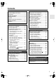
Contents Introduction ..................................... 2 5.1ch Home Theater System HT-SR750 AV Receiver (HT-R557) Front Speakers (SKF-645F) Center Speaker (SKC-645C) Surround Speakers (SKM-645S) Powered Subwoofer (SKW-540) Instruction Manual Connection .................................... 18 Turning On & First Time Setup..... 35 Basic Operation Playing your AV components ....... 41 Listening to the Radio .................. 43 Enjoying the Listening Modes .....
WARNING: TO REDUCE THE RISK OF FIRE OR ELECTRIC SHOCK, DO NOT EXPOSE THIS APPARATUS TO RAIN OR MOISTURE. CAUTION: TO REDUCE THE RISK OF ELECTRIC SHOCK, DO NOT REMOVE COVER (OR BACK). NO USER-SERVICEABLE PARTS INSIDE. REFER SERVICING TO QUALIFIED SERVICE PERSONNEL.
Precautions 1. Recording Copyright—Unless it’s for personal use only, recording copyrighted material is illegal without the permission of the copyright holder. 2. AC Fuse—The AC fuse inside the unit is not userserviceable. If you cannot turn on the unit, contact your Onkyo dealer. 3. Care—Occasionally you should dust the unit all over with a soft cloth. For stubborn stains, use a soft cloth dampened with a weak solution of mild detergent and water. Dry the unit immediately afterwards with a clean cloth.
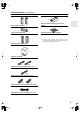
Speaker Precautions Package Contents Placement Make sure you have the following items: • The speaker cabinets are made out of wood and are therefore sensitive to extreme temperatures and humidity, do not put them in locations subject to direct sunlight or in humid places, such as near an air conditioner, humidifier, bathroom, or kitchen. • Do not put water or other liquids close to the speakers. If liquid is spilled over the speakers, the drive units may be damaged.
Package Contents—Continued Front speakers (SKF-645F) Base for horizontal mounting (For the center speaker) Center speaker (SKC-645C) Rubber spacers [20] (For the speakers) * In catalogs and on packaging, the letter at the end of the product name indicates the color. Specifications and operation are the same regardless of color. Surround speakers (SKM-645S) Subwoofer (SKW-540) (Red) (White) Speaker cable for front speakers 15 ft. (4.5 m) (Green) Speaker cable for center speaker 10 ft.
Features Amplifier • 5-channel amplifier • 110 watts per channel rms into 8 ohms, 2 channels driven at 1 kHz, less than 0.9% total harmonic distortion (FTC rating) • WRAT (Wide Range Amplifier Technology) • Non-Scaling Configuration • Massive High Current Power Supply (H.C.P.S.) transformer • Optimum Gain Volume Circuitry • Audyssey 2EQ room correction*1 *1 Manufactured under license from Audyssey Laboratories. U.S. and foreign patents pending. Audyssey 2EQ is a trademark of Audyssey Laboratories.
Contents Introduction Important Safety Instructions ....................2 Precautions .................................................3 Speaker Precautions ..................................4 Package Contents .......................................4 Features .......................................................6 Getting to Know the AV Receiver ..............9 Remote Controller.....................................12 Speakers ....................................................
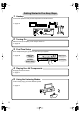
Getting Started in Five Easy Steps 1. Hookup Connect the speakers and your AV components to the AV receiver. ☞ page 18 IN 2 SIRIUS HDMI IN 1 OUT XM ANTENNA ASSIGNABLE AM FM 75 L DIGITAL IN ASSIGNABLE COAXIAL 1 Y (DVD) CBL/SAT 2 (CBL/SAT) CB/PB V CR/PR S VCR/DVR DVD MONITOR OUT V R S OPTICAL 1 (VCR/DVR) CBL/SAT IN VCR/DVR IN DVD IN OUT COMPONENT VIDEO 2 IN (CD) REMOTE CONTROL 2.
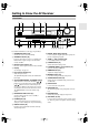
Getting to Know the AV Receiver Front Panel 1 2 3 4 5 6 7 MASTER VOLUME TUNING STANDBY/ON PRESET STANDBY DVD MULTI CH VCR/DVR CBL/SAT AUX TAPE TUNER CD SETUP ENTER RETURN AUX INPUT SETUP MIC PHONES DISPLAY DIGITAL INPUT TONE STEREO LISTENING MODE DIMMER VIDEO L AUDIO R MEMORY TUNING MODE CLEAR 8 9J K L M NOP Q R S T For detailed information, see the pages in parentheses. A STANDBY/ON button (35) Sets the AV receiver to On or Standby.
Getting to Know the AV Receiver—Continued Display 1 2 5 For detailed information, see the pages in parentheses. 1 MUTING indicator (45) Flashes while the AV receiver is muted. 2 Input signal format indicators Show the audio signal format of the current input source. 3 Listening mode indicators (48) Show the selected listening mode. 4 Radio indicators FM STEREO (43): Lights up when tuned to a stereo FM station.
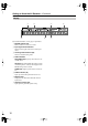
Getting to Know the AV Receiver—Continued Rear Panel 1 2 4 56 7 8 3 IN 2 OUT XM SIRIUS HDMI IN 1 9 ANTENNA ASSIGNABLE AM FM 75 L DIGITAL IN ASSIGNABLE COAXIAL 1 Y (DVD) CBL/SAT 2 (CBL/SAT) CB/PB V CR/PR S VCR/DVR DVD MONITOR OUT V R S OPTICAL 1 (VCR/DVR) CBL/SAT IN VCR/DVR IN DVD IN OUT COMPONENT VIDEO 2 IN (CD) OUT IN L R REMOTE CONTROL J CD L L R R TAPE K L IN OUT IN IN IN OUT IN FRONT SURROUND SPEAKERS FRONT SPEAKERS CENTER SPEAKER PRE OUT SUR
Remote Controller Installing the Batteries 1 To open the battery compartment, press the small hollow and slide open the cover. Aiming the Remote Controller When using the remote controller, point it toward the AV receiver’s remote control sensor, as shown below. Remote control sensor AV receiver STANDBY indicator 2 3 Insert the two supplied batteries (AA/R6) in accordance with the polarity diagram inside the battery compartment. Slide the cover shut.
Remote Controller—Continued Using the Remote Controller RECEIVER/TAPE Mode Including the AV receiver, the remote controller can be used to control up to seven different components. The remote controller has a specific operating mode for use with each type of component. Modes are selected by using the six REMOTE MODE buttons. ■ RECEIVER/TAPE Mode In RECEIVER/TAPE mode, you can control the AV receiver and an Onkyo cassette recorder connected via . RECEIVER/TAPE mode is used to control the AV receiver.
Remote Controller—Continued For detailed information, see the pages in parentheses. A STANDBY/ON button (35) Sets the AV receiver to On or Standby. ■ Buttons used when the TUNER input is selected To select the Tuner (AM/FM) as the input source, press: B INPUT SELECTOR buttons (41) Used to select the input sources. RECEIVER 8 TUNER C MULTI CH button (42) Selects the multichannel DVD input. D DIMMER button (45) Adjusts the display brightness.
Remote Controller—Continued A STANDBY/ON button DVD Mode Sets the DVD player to On or Standby. By default, the remote controller is set to control an Onkyo DVD player. To select your DVD player as the input source, press: RECEIVER or 6 DVD B Number buttons Used to enter title, chapter, and track numbers and times for locating specific points. C DISC +/– button Selects discs on a DVD changer. 5 D TOP MENU button MULTI CH Selects a DVD’s top menu.
Remote Controller—Continued A STANDBY/ON button CD/MD/CDR/DOCK Mode Sets the component to On or Standby. By default, the remote controller is set to control an Onkyo CD player. To select the input source, press: 9 MD or CD recorder 7 TAPE 7 Used to enter track numbers and times for locating specific points on CD/MD players.
Speakers Subwoofer (SKW-540) For detailed information, see the pages in parentheses. A STANDBY/ON indicator ■ Front Red: Subwoofer in standby mode Green: Subwoofer on With the Auto Standby function, the SKW-540 automatically turns on when an input signal is detected in Standby mode. When there’s no input signal for a while, the SKW-540 automatically enters Standby mode. B OUTPUT LEVEL control (41) 1 This control is used to adjust the volume of the subwoofer.
Connecting Your Speakers Enjoying Home Theater Thanks to the AV receiver’s superb capabilities, you can enjoy surround sound with a real sense of movement in your own home—just like being in a movie theater or concert hall. You can enjoy DVDs featuring DTS and Dolby Digital. With analog and digital TV, you can enjoy Dolby Pro Logic II and Onkyo’s own DSP surround listening modes.
Connecting Your Speakers—Continued Speaker Connection Precautions Read the following before connecting your speakers: • You can connect speakers with an impedance of between 8 and 16 ohms. If you use speakers with a lower impedance, and use the amplifier at high volume levels for a long period of time, the built-in amp protection circuit may be activated. • Disconnect the power cord from the wall outlet before making any connections. • Pay close attention to speaker wiring polarity.
Connecting Your Speakers—Continued Center Speaker Base Wall Mounting Use the center speaker base to mount the center speaker horizontally. If you place the speaker and its base on top of a TV or an entertainment center, adjust the angle of the speaker so that it faces toward the listening position. The center speaker should be installed on the base securely. If the speaker is loose, try adjusting the position so that it sits securely on the base.
Connecting Antennas This section explains how to connect the supplied indoor FM antenna and AM loop antenna, and how to connect commercially available outdoor FM and AM antennas. The AV receiver won’t pick up any radio signals without any antenna connected, so you must connect the antenna to use the tuner. AM antenna push terminals FM antenna jack AM OUT 1 Assemble the AM loop antenna, inserting the tabs into the base, as shown.
Connecting Antennas—Continued Connecting an Outdoor FM Antenna Connecting an Outdoor AM Antenna If you cannot achieve good reception with the supplied indoor FM antenna, try a commercially available outdoor FM antenna instead. If good reception cannot be achieved using the supplied AM loop antenna, an outdoor AM antenna can be used in addition to the loop antenna, as shown.
Connecting Your Components AV Connection Color Coding About AV Connections RCA-type AV connections are usually color coded: red, white, and yellow. Use red plugs to connect right-channel audio inputs and outputs (typically labeled “R”). Use white plugs to connect left-channel audio inputs and outputs (typically labeled “L”). And use yellow plugs to connect composite video inputs and outputs. • Before making any AV connections, read the manuals supplied with your other AV components.
Connecting Your Components—Continued Connecting Audio and Video Signals to the AV Receiver By connecting both the audio and video outputs of your DVD player and other AV components to the AV receiver, you can switch the audio and video signals simultaneously simply by changing the input source on the AV receiver. : Signal Flow Video Video Audio Audio Speakers (see page 19 for hookup details) TV, projector, etc. DVD player, etc.
Connecting Your Components—Continued Connecting a TV or Projector Step 1: Choose a video connection from A , B , and C . Step 2: Choose an audio connection from a , b , and c . • With connection a , you can listen to and record audio from your TV and listen via speaker set B. • To enjoy Dolby Digital and DTS, use connection b or c . (For recording, use a and b , or a and c .
Connecting Your Components—Continued Connecting a DVD player Step 1: Choose a video connection from A , B , and C . You must connect the AV receiver to your TV via the same type of connection. Step 2: Choose an audio connection from a , b , and c . • With connection a , you can listen to and record audio from a DVD and listen via speaker set B. • To enjoy Dolby Digital and DTS, use connection b or c . (For recording, use a and b , or a and c .
Connecting Your Components—Continued Hooking Up the Multichannel DVD Input If your DVD player supports multichannel audio formats such as DVD-Audio or SACD, and it has a multichannel analog audio output, you can connect it to the AV receiver’s multichannel DVD input. Use a multichannel analog audio cable, or several normal audio cables, to connect the AV receiver’s DVD IN FRONT L/R, CENTER, SURROUND L/R, and SUBWOOFER jacks to the 5.1-channel analog audio output on your DVD player.
Connecting Your Components—Continued Connecting Components with HDMI If you have an HDMI-compatible player, you can connect it to the AV receiver with an HDMI cable. Step 1: Connect your HDMI-compatible TV to the AV receiver’s HDMI OUT jack. Step 2: Connect your HDMI-compatible player to the AV receiver’s HDMI IN 1 or 2 jack. Step 3: Connect your HDMI-compatible player to an analog and/or digital audio input on the AV receiver.
Connecting Your Components—Continued Connecting a VCR or DVD Recorder for Playback Hint! With this hookup, you can use your VCR’s tuner to listen to your favorite TV programs via the AV receiver, useful if your TV has no audio outputs. Step 1: Choose a video connection from A , B , and C . You must connect the AV receiver to your TV via the same type of connection. Step 2: Choose an audio connection from a , b , and c .
Connecting Your Components—Continued Connecting a VCR or DVD Recorder for Recording Step 1: Choose a video connection from A and B . The video source to be recorded must be connected to the AV receiver via the same type of connection. Step 2: Make the audio connection a .
Connecting Your Components—Continued Connecting a Satellite, Cable, Set-top box, or Other Video Source Hint! With this hookup, you can use your satellite or cable receiver to listen to your favorite TV programs via the AV receiver, useful if your TV has no audio outputs. Step 1: Choose a video connection from A , B , and C . You must connect the AV receiver to your TV via the same type of connection. Step 2: Choose an audio connection from a , b , and c .
Connecting Your Components—Continued Connecting a CD Player or Turntable ■ CD Player or Turntable (MM) with Built-in Phono Preamp Step 1: Choose a connection that matches your CD player ( a , b , or c ). Use connection a for a turntable with a built-in phono preamp.
Connecting Your Components—Continued Connecting an RI Dock ■ RI Dock with video Connect your RI Dock’s analog audio output jacks and S-Video output jack to the AV receiver’s CBL/SAT IN L/R jacks and CBL/SAT IN S jack. S VIDEO OUT AUDIO OUT L ■ RI Dock without video Connect your RI Dock’s analog audio output jacks to the AV receiver’s TAPE IN L/R jacks (1).
Connecting Your Components—Continued Connecting Onkyo Components Step 1: Make sure that each Onkyo component is connected to the AV receiver with an analog audio cable (connection a in the hookup examples) (see pages 26 to 33). Step 2: Make the connection. Step 3: If you’re using an MD, CDR, or RI Dock, change the input Display (see page 40).
Turning On the AV Receiver STANDBY/ON STANDBY/ON STANDBY indicator REMOTE MODE STANDBY/ON DVD RECEIVER TAPE/AMP INPUT SELECTOR RECEIVER 1 2 VCR/DVR CBL/SAT M D/CDR CD 3 DOCK MASTER VOLUME TUNING STANDBY/ON PRESET 4 5 6 AUX MULTI CH DVD 7 STANDBY 8 TAPE MULTI CH DVD VCR/DVR CBL/SAT AUX TAPE TUNER CD SETUP ENTER CD 11 12 +10 0 --/--- DIMMER SLEEP VOL DISC ALBUM D TUN RETURN VCR 9 TUNER 10 TV CLR CABLE SAT ENT AUX INPUT SETUP MIC PHONES DISPLAY DIGI
First Time Setup This section explains the settings that you need to make before using the AV receiver for the very first time. Automatic Speaker Setup (Audyssey 2EQ) With the supplied speaker setup microphone, the Audyssey 2EQ function can measure the number of speakers connected, their sizes, crossover frequencies, and distances from the listening position, and then calculate the optimal speaker settings for your listening environment.
First Time Setup—Continued Using Audyssey 2EQ 1 MASTER VOLUME TUNING STANDBY/ON PRESET STANDBY MULTI CH DVD VCR/DVR CBL/SAT AUX TAPE TUNER CD SETUP ENTER RETURN AUX INPUT SETUP MIC PHONES DISPLAY DIGITAL INPUT TONE STEREO LISTENING MODE DIMMER VIDEO L AUDIO R MEMORY TUNING MODE CLEAR 2, 6 Notes: • If the AV receiver was previously muted, it will be unmuted. • Automatic speaker setup cannot be performed while a pair of headphones is connected.
First Time Setup—Continued Error Messages Changing the Speaker Settings Manually While the automatic speaker setup is in progress, one of the following error messages may appear: In some situations, the measurements taken by the automatic speaker setup may not provide usable results. If running the speaker setup a second time still doesn’t provide usable results, you’ll have to set the speaker settings manually (see pages 53–57).
First Time Setup—Continued HDMI Video Setup If you connect a video component to HDMI IN 1 or 2, use this setting to assign that input to an input selector. 1 RECEIVER STANDBY/ON Press the [RECEIVER] button, followed by the [SETUP] button.
First Time Setup—Continued Digital Audio Input Setup 2, 3 Changing the Input Display 1 MASTER VOLUME TUNING STANDBY/ON PRESET STANDBY DVD MULTI CH VCR/DVR CBL/SAT AUX TAPE TUNER CD SETUP ENTER If you connect an -capable Onkyo MiniDisc recorder, CD recorder, or RI Dock to the TAPE IN/OUT or CBL/SAT IN jacks, for to work properly, you must change this setting. This setting can only be changed on the AV receiver.
Playing Your AV Components Basic AV Receiver Operation 3 1 MULTI CH STANDBY/ON REMOTE MODE DVD RECEIVER TAPE/AMP MASTER VOLUME TUNING STANDBY/ON 1 INPUT SELECTOR 1 2 1 M D/CDR Subwoofer’s rear panel CD 3 DOCK VCR/DVR PRESET CBL/SAT 4 5 6 AUX MULTI CH DVD 7 8 TV STANDBY TAPE CBL/SAT AUX TAPE TUNER CD SETUP ENTER RETURN DISPLAY DIGITAL INPUT TONE STEREO LISTENING MODE DIMMER VIDEO L AUDIO CD 11 12 +10 0 --/--- DIMMER SLEEP VOL DISC ALBUM CLR D TUN A
Playing Your AV Components—Continued Displaying Source Information STANDBY/ON REMOTE MODE DVD RECEIVER TAPE/AMP INPUT SELECTOR 1 2 VCR/DVR CBL/SAT RECEIVER M D/CDR You can display various information about the current input source as follows.
Listening to the Radio Tuning into AM/FM Radio Stations Listening to AM/FM Stations ■ Auto Tuning Mode TUNER TUNING 1 TUNING MODE MASTER VOLUME TUNING STANDBY/ON PRESET Press the [TUNING MODE] button so that the AUTO indicator appears on the display.
Listening to the Radio—Continued ■ Tuning into Stations by Frequency You can tune into AM and FM stations directly by entering the appropriate frequency. STANDBY/ON 1 Press the [MEMORY] button. The preset number flashes.
Common Functions This section explains functions that can be used with any input source. Adjusting the Bass and Treble You can adjust the bass and treble for the front speakers, except when the Direct listening mode is selected.
Common Functions—Continued Using the Sleep Timer Adjusting Speaker Levels With the sleep timer, you can set the AV receiver so that it turns off automatically after a specified period. SLEEP You can adjust the volume of each speaker in speaker set A. These temporary adjustments are cancelled when the AV receiver is set to Standby. Press the remote controller’s [SLEEP] button repeatedly to select the required sleep time. You can set the sleep time from 90 to 10 minutes in 10 minute steps.
Using the Listening Modes Selecting with the Remote Controller Selecting Listening Modes TV For a description of each listening mode, see “About the Listening Modes” on page 48. • While a pair of headphones is connected, you can select only the Mono, Direct, or Stereo listening mode.
Using the Listening Modes—Continued The following table shows which listening modes can be used with each input signal format. Source format 3/2.1 2/2.1 CD, TV, radio, cassette, etc. Listening mode DTS/DTS 96/24*2 Dolby Digital Analog, PCM*1 2/0 1/0, 1+1 Other 3/2.1 2/2.1 DVD, DTV, etc. DTS-ES 2/0 Discrete Matrix DVD, CD, etc.
Using the Listening Modes—Continued Dolby Pro Logic II Movie Use this mode with DVDs and videos that bear the Dolby Surround logo or TV shows that feature Dolby Surround. You can also use this mode with stereo movies or TV shows and the AV receiver will create a 5.1 surround mix from the 2-channel stereo. detailed sound stage, with superior channel separation and localization of audio elements. System playback is scalable from 5.1 to 7.1 multichannel surround playback.
Using the Listening Modes—Continued Using the CinemaFILTER STANDBY/ON REMOTE MODE DVD RECEIVER RECEIVER TAPE/AMP INPUT SELECTOR 1 2 VCR/DVR CBL/SAT M D/CDR CD 3 DOCK 4 5 6 AUX MULTI CH DVD 7 8 TAPE TV VCR 9 TUNER 10 CD 11 12 +10 0 --/--- DIMMER SLEEP VOL DISC ALBUM CLR D TUN CABLE With the CinemaFILTER, you can soften overly bright movie soundtracks, which are typically mixed for reproduction in a movie theater.
Using the Listening Modes—Continued 4 Press the [SETUP] button. Setup closes. SETUP The Audio Adjust settings are explained below. Input Channel Settings ■ Multiplex This setting determines which channel is output from a stereo multiplex source. Use it to select audio channels or languages with multiplex sources, multilingual TV broadcasts, and so on. Main: The main channel is output (default). Sub: The sub channel is output. M/S: Both the main and sub channels are output.
Recording This section explains how to record the selected input source to a component with recording capability, and how to record audio and video from different sources. Recording the Input Source You can only record to a component that’s connected to the TAPE OUT or VCR/DVR OUT jacks. See pages 23–34 for information on connecting your AV components.
Advanced Setup Advanced Speaker Settings 4 This section explains how to check the speaker settings and how to set them manually, which is useful if you change a speaker after performing the automatic speaker setup. Some speaker settings are set automatically by the Automatic Speaker Setup function (see page 36).
Advanced Setup—Continued Crossover Frequency Double Bass If you’re using speakers other than those included with this home theater system, to get the best bass performance from your speaker system, you need to set the crossover frequency according to the size and frequency response of your speakers. This setting is set automatically by the Automatic Speaker Setup function (see page 36). This setting only applies to the speakers that you specified as Small in the “Speaker Configuration” on page 53.
Advanced Setup—Continued Speaker Distance These settings are set automatically by the Automatic Speaker Setup function (see page 36). 7 Press the [SETUP] button. Setup closes. SETUP With these settings, you can specify the distance from each speaker to the listening position. 1 2 Measure and make a note of the distance from each speaker to the listening position. RECEIVER Press the [RECEIVER] REMOTE MODE button, followed by the [SETUP] button.
Advanced Setup—Continued Speaker Levels These settings are set automatically by the Automatic Speaker Setup function (see page 36). You can set the volume level of each speaker so that all speakers can be heard equally at the listening position. 1 RECEIVER Press the [RECEIVER] REMOTE MODE button, followed by the [SETUP] button. SETUP 56 2 Use the Up and Down [ ]/[ ] buttons to select “Level Cal,” and then press [ENTER]. A pink noise test tone is output by the front left speaker.
Advanced Setup—Continued Equalizer Settings 5 Use the Up and Down [ ]/[ ] buttons to select a frequency. Use the Left and Right [ ]/[ ] buttons to adjust the level at that frequency. These settings are set automatically by the Automatic Speaker Setup function (see page 36). Here you can adjust the tone of individual speakers. To set the volume of individual speakers, see page 56. 1 RECEIVER Press the [RECEIVER] REMOTE MODE button, followed by the [SETUP] button.
Advanced Setup—Continued Digital Input Signal Formats Correcting Sound and Picture Sync The following table shows the display indicator for each digital signal format. Format Display Dolby Digital When using progressive scanning on your DVD player, you may find that the picture and sound are out of sync. With this setting, you can correct this by delaying the audio signals. You can set it from 0 to 100 milliseconds (ms) in 20 millisecond steps.
Controlling Other Components You can use the AV receiver’s remote controller (RC-681M) to control your other AV components, including those made by other manufacturers. This section explains how to enter the necessary remote control code for the component that you want to control (e.g., DVD player, TV, or VCR). 1 Look up the appropriate remote control code in the separate Remote Control Codes list. The codes are organized by category (e.g., DVD player, TV, etc.).
Controlling Other Components—Continued Remote Control Codes for Onkyo Components Connected via Onkyo components that are connected via are controlled by pointing the remote controller at the AV receiver, not the component. This allows you to control components that are out of view, in a rack, for example. Resetting REMOTE MODE Buttons You can reset a REMOTE MODE button to its default remote control code.
Controlling Other Components—Continued To control another component, point the remote controller at it and use the buttons explained below. (You must select the appropriate remote control mode first.) With some AV components, certain buttons may not work as expected, and some may not work at all.
Troubleshooting If you have any trouble using the AV receiver, look for a solution in this section. If you can’t resolve the issue yourself, try resetting the AV receiver before contacting your Onkyo dealer. To reset the AV receiver to its factory defaults, turn it on and, while holding down the [VCR/DVR] button, press the [STANDBY/ON] button. “Clear” will appear on the display and the AV receiver will enter Standby mode.
Troubleshooting—Continued The center speaker produces no sound • When the Stereo or Mono listening mode is selected, the center speaker produces no sound (page 48). • Make sure the speakers are configured correctly (page 53). The subwoofer produces no sound • When you play source material that contains no information in the LFE channel, the subwoofer produces no sound. • Make sure the speakers are configured correctly (page 53).
Troubleshooting—Continued • Make sure you’ve selected the correct remote controller mode (page 13). • Make sure you’ve entered the correct remote control code (page 59). During automatic speaker setup, measurement fails and the message “Noise Error!” appears • This can be caused by a speaker malfunction. Make sure all of your speakers are working properly. Can’t control other components • Make sure you’ve selected the correct remote controller mode (page 13).
Specifications AV Receiver (HT-R557) ■ Amplifier Section ■ General Rated Output Power (FTC) All channels: 110 watts minimum continuous power per channel, 8 ohm loads, 2 channels driven at 1 kHz, with a maximum total harmonic distortion of 0.9% Rated Output Power (IEC) 5 ch × 130 W at 8 ohms, 1 kHz, 1 ch driven Maximum Output Power (JEITA) 5 ch × 160 W at 8 ohms, 1 kHz, 1 ch driven Dynamic Power 210 W (3Ω, 1 ch driven) 190 W (4Ω, 1 ch driven) 130 W (8Ω, 1 ch driven) THD (Total Harmonic Distortion) 0.
Specifications—Continued 5.1ch Home Theater Speaker Package (HTP-645) ■ Powered Subwoofer (SKW-540) ■ Center Speaker (SKC-645C) Type: Bass-reflex Input sensitivity/ impedance: 330 mV / 100 kΩ Maximum output power: 230 W (Dynamic Power) Frequency response: 25 Hz–150 Hz Cabinet capacity: 1.36 cubic feet (38.5 L) Dimensions (W × H × D): 10-13/16" × 18-5/8" × 17-11/16" (275 × 473 × 449 mm) Weight: 25.4 lbs. (11.
Memo 67
Sales & Product Planning Div. : 2-1, Nisshin-cho, Neyagawa-shi, OSAKA 572-8540, JAPAN Tel: 072-831-8023 Fax: 072-831-8124 ONKYO U.S.A. CORPORATION 18 Park Way, Upper Saddle River, N.J. 07458, U.S.A. Tel: 201-785-2600 Fax: 201-785-2650 http://www.us.onkyo.com/ ONKYO EUROPE ELECTRONICS GmbH Liegnitzerstrasse 6, 82194 Groebenzell, GERMANY Tel: +49-8142-4401-0 Fax: +49-8142-4401-555 http://www.eu.onkyo.