Contents AV RECEIVER HT-R592 Safety Information and Introduction ............2 Table of Contents ...........................................5 Connections .................................................11 Turning On & Basic Operations..................18 Instruction Manual Advanced Operations ..................................36 Controlling Other Components...................51 Appendix .......................................................
Safety Information and Introduction WARNING: TO REDUCE THE RISK OF FIRE OR ELECTRIC SHOCK, DO NOT EXPOSE THIS APPARATUS TO RAIN OR MOISTURE. CAUTION: TO REDUCE THE RISK OF ELECTRIC SHOCK, DO NOT REMOVE COVER (OR BACK). NO USER-SERVICEABLE PARTS INSIDE. REFER SERVICING TO QUALIFIED SERVICE PERSONNEL.
Safety Information and Introduction Precautions 1. Recording Copyright—Unless it’s for personal use only, recording copyrighted material is illegal without the permission of the copyright holder. 2. AC Fuse—The AC fuse inside the unit is not userserviceable. If you cannot turn on the unit, contact your Onkyo dealer. 3. Care—Occasionally you should dust the unit all over with a soft cloth. For stubborn stains, use a soft cloth dampened with a weak solution of mild detergent and water.
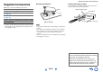
Safety Information and Introduction Supplied Accessories ■ Installing the batteries Make sure you have the following accessories: Indoor FM antenna (➔ page 17) ■ Aiming the remote controller To use the remote controller, point it at the AV receiver’s remote control sensor, as shown below.
Safety Information and Introduction Table of Contents Safety Information and Introduction Important Safety Instructions ......................................2 Precautions ...................................................................3 Supplied Accessories...................................................4 Table of Contents..........................................................5 Features .........................................................................6 Front & Rear Panels.................
Safety Information and Introduction Features Amplifier • 80 Watts/Channel @ 8 ohms (FTC) • 130 Watts/Channel @ 6 ohms (IEC) • 160 Watts/Channel @ 6 ohms (JEITA) • Optimum Gain Volume Circuitry • H.C.P.S. (High Current Power Supply) Massive High Power Transformer Processing • HDMI (Audio Return Channel, 3D, DeepColor, x.v.
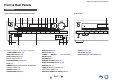
Safety Information and Introduction Front & Rear Panels Front Panel (North American, Brazilian and Taiwanese models) For detailed information, see the pages in parentheses.
Safety Information and Introduction Display For detailed information, see the pages in parentheses. Z2 (Zone 2) indicator (50) 3D indicator This lights when a 3D input signal is detected.
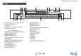
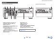
Safety Information and Introduction Rear Panel (North American and Asian models) (Brazilian and Taiwanese models) DIGITAL IN COAXIAL and OPTICAL jacks MONITOR OUT V jack COMPONENT VIDEO IN and OUT jacks ZONE 2 LINE OUT jacks HDMI IN and OUT jacks SUBWOOFER PRE OUT jack SPEAKERS terminals (CENTER, FRONT, SURROUND, SURROUND BACK or FRONT HIGH, ZONE 2) Power cord (North American and Asian models) AC INLET (Brazilian and Taiwanese models) FM ANTENNA jack and AM ANTENNA terminal REMOTE CONTROL jack C
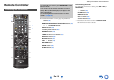
Safety Information and Introduction Remote Controller To control the AV receiver, press RECEIVER to select Receiver mode. You can also use the remote controller to control Onkyo Blu-ray Disc/DVD player, CD player, and other components. See “Entering Remote Control Codes” for more details (➔ page 53). Controlling the AV Receiver *1 For detailed information, see the pages in parentheses.
Connections Connecting the AV Receiver Surround back/ front high right Surround back/ front high left Surround right Surround left Center Connecting Your Speakers Speaker Configuration The following table indicates the channels you should use depending on the number of speakers that you have. No matter how many speakers you use, a powered subwoofer is recommended for a really powerful and solid bass.
Connections Connecting the Speaker Cables The speaker terminals are color-coded for identification purpose. Speaker Color Front left, Zone 2 left White Front right, Zone 2 right Red Center Green Surround left Blue Surround right Gray Surround back left, Front high left Brown Surround back right, Front high right Tan • Be careful not to short the positive and negative wires. Doing so may damage the AV receiver.
Connections AV Cables and Jacks About AV Connections ■ HDMI HDMI connections can carry digital video and audio. Connecting AV components a HDMI cable ■ Optical digital audio Optical digital connections allow you to enjoy digital sound such as PCM*1, Dolby Digital or DTS. The audio quality is the same as coaxial. : Video & Audio TV, projector, etc.
Connections Connecting Components with HDMI VCR or DVD recorder/digital video recorder Game console TV, projector, etc. Satellite/cable set-top box, etc. * * Blu-ray Disc/DVD player If your TV doesn’t support Audio Return Channel (ARC), you need to connect an optical digital cable together with the HDMI cable to the AV receiver.
Connections Connecting Your Components The on-screen menus appear only on a TV that is connected to the HDMI OUT. If your TV is connected to other video outputs, use the AV receiver’s display when changing settings. Note *1 *2 ✔: Assignment can be changed (➔ pages 38, 39). No. Jack/Port Components *3 AUX INPUT VIDEO Camcorder, etc.
Connections Connecting Onkyo RI Components 1 Make sure that each Onkyo component is connected with an analog audio cable (connection in the hookup examples) (➔ page 15). 2 3 Make the Connecting a Recording Component See “Recording” for details on recording (➔ page 35). connection (see the illustration). If you’re using an RI Dock or cassette tape deck, change the Input Display (➔ page 35). With (Remote Interactive), you can use the following special functions: e.g.
Connections Connecting the Antennas Connecting the Power Cord This section explains how to connect the supplied indoor FM antenna and AM loop antenna. The AV receiver won’t pick up any radio signals without any antenna connected, so you must connect the antenna to use the tuner. North American, Brazilian and Taiwanese models 1 (Brazilian and Taiwanese models) Connect the supplied power cord to the AV receiver’s AC INLET. Asian models To AC wall outlet Push. Insert wire. Release.
Turning On & Basic Operations Turning On/Off the AV Receiver Turning On 1 Press or Turning Off ON/STANDBY on the front panel. 1 Press or ON/STANDBY on the front panel. ON/STANDBY Press RECEIVER followed by on the remote controller. The AV receiver comes on, and its display lights. Press RECEIVER followed by on the remote controller. The AV receiver will enter standby mode. To prevent any loud surprises when you turn on the AV receiver, always turn down the volume before you turn it off.
Turning On & Basic Operations Playback The on-screen menus appear only on a TV that is connected to the HDMI OUT. If your TV is connected to other video outputs, use the AV receiver’s display when changing settings. Playing the Connected Component ■ Operating on the AV receiver Input selector buttons ■ Operating with the remote controller LISTENING MODE MASTER VOLUME INPUT SELECTOR RECEIVER This section describes the procedure for using the remote controller unless otherwise specified.
Turning On & Basic Operations Controlling Contents of USB Devices TOP MENU RANDOM This button displays the top menu for each media or service. This button performs random playback. / and ENTER REPEAT These buttons navigate through the menus. Press this button repeatedly to cycle through the repeat modes. / This button cycles through pages. Press USB first. PLAYLIST / In Standard Mode (iPod/iPhone), this button selects playlists.
Turning On & Basic Operations Understanding Icons on the Display This section describes icons that appear on the AV receiver’s display during media playback. Icon Playing an iPod/iPhone via USB The on-screen menus appear only on a TV that is connected to the HDMI OUT. Description Folder Track Playback Pause This section explains how to play music files on the iPod/iPhone.
Turning On & Basic Operations Playing a USB Device The on-screen menus appear only on a TV that is connected to the HDMI OUT. This section explains how to play music files from a USB device (e.g., USB flash drives and MP3 players). See also: • “USB Features” (➔ page 66). 1 2 Press USB to select the “USB” input. Plug your USB device into the AV receiver’s USB port. While reading the contents of your USB device, the message “Connecting...” appears on the AV receiver’s display. 3 Press ENTER.
Turning On & Basic Operations Listening to AM/FM Radio This section describes the procedure using the buttons on the front panel unless otherwise specified. Using the Tuner With the built-in tuner you can enjoy AM and FM radio stations. You can store your favorite stations as presets for quick selection. You can also change the frequency steps (➔ page 45). 1 ■ Auto tuning mode 1 Press TUNING MODE so that the AUTO indicator lights on the AV receiver’s display. 2 Press TUNING / .
Turning On & Basic Operations Presetting AM/FM Stations ■ Selecting Presets You can store a combination of up to 40 of your favorite AM/FM radio stations as presets. 1 1 Tune into the AM/FM station that you want to store as a preset. See the previous section. 2 Press MEMORY. The preset number flashes. (Actual display depends on the country.) 3 While the preset number is flashing (about 8 seconds), use PRESET / to select a preset from 1 through 40.
Turning On & Basic Operations Note • In some cases, the text characters displayed on the AV receiver may not be identical to those broadcast by the radio station. Also, unexpected characters may be displayed when unsupported characters are received. This is not a malfunction. • If the signal from an RDS station is weak, RDS data may be displayed intermittently or not at all. ■ Listening to Traffic News (TP) RDS program types (PTY) You can search for stations that broadcast traffic news.
Turning On & Basic Operations Using Basic Functions Using the Automatic Speaker Setup With the supplied calibrated microphone, Audyssey 2EQ® automatically determines the number of speakers connected, their size for purposes of bass management, optimum crossover frequencies to the subwoofer (if present), and distances from the primary listening position.
Turning On & Basic Operations 1 Turn on the AV receiver and the connected TV. On the TV, select the input to which the AV receiver is connected. 3 When you’ve finished making the settings, press ENTER. Powered Zone 2 SurrBk/FrontHigh Subwoofer • Before plugging the Speaker setup microphone to perform Automatic Speaker Setup, please make sure that all your connected speakers and subwoofers produce sound. 2 Press ENTER. Audyssey 2EQ® Room Correction and Speaker Setup starts.
Turning On & Basic Operations Tip • You can view the calculated settings for the speaker configuration, speaker distances, and speaker levels by using / . 10 Use / to select a target, and use / to change the setting. After the results of Audyssey 2EQ have been saved, the menu will display the “Audyssey” (➔ page 42), “Dynamic EQ” (➔ page 43), “Dynamic Volume” (➔ page 43) settings. Note • When “Audyssey Quick Start” has been used for measurement, “Audyssey” cannot be selected.
Turning On & Basic Operations MOVIE/TV button This button selects the listening modes intended for use with movies and TV. MUSIC button This button selects the listening modes intended for use with music. GAME button This button selects the listening modes intended for use with video games. STEREO button This button selects the Stereo listening mode and All Channel Stereo listening mode.
Turning On & Basic Operations About Listening Modes The AV receiver’s listening modes can transform your listening room into a movie theater or concert hall, with high fidelity and stunning surround sound. ■ Explanatory Notes Input Source The following audio formats are supported by the listening mode. This is mono (monophonic) sound. This is stereo (stereophonic) sound. Two independent audio signal channels are reproduced through two speakers. This is 5.1-channel surround sound.
Turning On & Basic Operations ■ Onkyo-Original DSP Listening Modes Listening Mode Description Orchestra*1 Suitable for classical or operatic music, this mode emphasizes the surround channels in order to widen the stereo image, and simulates the natural reverberation of a large hall.
Turning On & Basic Operations Listening Mode Description DSD*3 In this mode, audio from the input source is output without surround-sound processing. The speaker configuration (presence of speakers), crossover frequency, speaker distance, A/V Sync and much of the processing set via Home menu are enabled. See “On-screen Setup” for more details (➔ page 36).
Turning On & Basic Operations Listening Mode Dolby Pro Logic IIz Height PL z He i g h t Dolby EX Do l b y EX Do l b y D EX DTS Neo:6 Ne o : 6 C i n ema Ne o : 6 Mu s i c Ne o : 6 Description Dolby Pro Logic IIz Height is designed to more effectively use existing program material when height channel speaker outputs are present. Dolby Pro Logic IIz Height can be used to upmix a variety of sources from movies and music, but are particularly well-suited to upmix game content. These modes expand 5.
Turning On & Basic Operations ■ Information*1 ` You can view the information of the following items: “Input” and “Output”. Using the Home Menu The Home menu provides quick access to frequently used settings. You can change settings and view the current information. ■ Listening Mode*2 ` You can select the listening modes that are grouped in the following categories: “MOVIE/TV”, “MUSIC” and “GAME”. Use / to select the category and / to select the listening mode.
Turning On & Basic Operations Displaying Source Information You can display various information about the current input source as follows. 1 Press RECEIVER once followed by DISPLAY repeatedly to cycle through the available information. Changing the Input Display When you connect an -capable Onkyo component, you must configure the input display so that can work properly. 1 Tip Using Headphones 1 Note Change the name of the input selector to “DOCK” or “TAPE”.
Advanced Operations On-screen Setup Explanatory Notes Common Procedures in Setup Menu The setup menus provides a convenient way to change the AV receiver’s various settings. Settings are organized into 10 categories. Menu Remote indicator The on-screen menus appear only on a TV that is connected to the HDMI OUT. If your TV is connected to other video outputs, use the AV receiver’s display when changing settings.
Advanced Operations Setup menu items Menu item Setting target Menu item Setting target 5. Sp Distance (➔ page 40) Unit 9. Hardware (➔ page 45) Volume OSD Left Menu item Setting target 1. HDMI Input (➔ page 38) BD/DVD Front High Left VCR/DVR Center CBL/SAT Front High Right 2. Component (➔ page 38) Auto Standby [HDMI Through] 10.
Advanced Operations 1. HDMI Input 1 2 Menu 3 Note 4 5 6 HDMI Input If you connect a video component to an HDMI input, you must assign that input to an input selector. For example, if you connect your Blu-ray Disc/DVD player to HDMI IN 2, you must assign “HDMI2” to the “BD/DVD” input selector. Here are the default assignments.
Advanced Operations 3. Digital Audio (Digital Audio Input) 1 2 Menu 3 4 5 6 Digital Audio If you connect a component to a digital audio input, you must assign that input to an input selector. For example, if you connect your CD player to the COAXIAL IN 1, you must assign “COAXIAL1” to the “TV/CD” input selector. Here are the default assignments.
Advanced Operations Note *1 *2 *3 *4 *5 If the “Front” setting is set to “Small”, the “Large” option cannot be selected. If the “Surround” setting is set to “None”, this setting cannot be selected. If the “Surround” setting is set to “Small”, the “Large” option cannot be selected. If the “Surround Back” setting is set to other than “None”, this setting is set to “None”. If the “Front High” setting is set to other than “None”, this setting is set to “None”.
Advanced Operations 6. Level Cal (Level Calibration) 1 2 Menu 3 4 5 Dolby 7. Audio Adjust 6 Level Cal This setting is set automatically by Audyssey 2EQ® Room Correction and Speaker Setup (➔ page 26). Here you can adjust the level of each speaker with the built-in test tone so that the volume of each speaker is the same at the listening position. Note • These settings cannot be calibrated in either of the following cases: – A pair of headphones is connected.
Advanced Operations ■ PL IIz Height Gain ` Low ` Mid ` High The Height Gain Control in Dolby Pro Logic IIz enables the listener to select how much gain is applied to the front high speakers. There are three settings, “Low”, “Mid” and “High”, and the front high speakers are accentuated in that order. While “Mid” is the default listening setting, the listener may adjust the Height Gain Control to their personal preference.
Advanced Operations ■ Dynamic EQ ` Off ` On: Audyssey Dynamic EQ® becomes active. The Dynamic EQ indicator lights. With Audyssey Dynamic EQ, you can enjoy great sound even when listening at low volume levels. Audyssey Dynamic EQ solves the problem of deteriorating sound quality as volume is decreased by taking into account human perception and room acoustics.
Advanced Operations A/V Sync Audio Selector ■ A/V Sync ` 0 ms to 400 ms in 10 msec steps. When using progressive scanning on your Blu-ray Disc/DVD player, you may find that the picture and sound are out of sync. With this setting, you can correct this by delaying the audio signals. Press ENTER to view the TV picture while setting the delay when the video source is output to HDMI OUT. To return to the previous screen, press RETURN.
Advanced Operations Tuner . 9. Hardware 1 2 Menu 3 4 5 6 Hardware OSD ■ AM/FM Freq Step (North American, Brazilian and Taiwanese models) ` 10kHz/200kHz: ` 9kHz/50kHz: Select the frequency step according to your area. ■ Volume OSD ` On ` Off Turn this setting on to display the volume level on the TV screen while it is adjusted. ■ AM Freq Step (Asian models) ` 10kHz: ` 9kHz: Select the frequency step according to your area.
Advanced Operations • When the source equipment is connected with the connection, it may malfunction if “HDMI CEC (RIHD)” is set to “On”. 10. HDMI Setup 1 Menu 2 3 4 5 6 HDMI Setup ■ HDMI CEC (RIHD) ` Off ` On Turn this setting on to allow -compatible components connected via HDMI to be controlled by the AV receiver (➔ page 63). Note • When the setting is set to “On” and the menu is closed, the names of connected -compatible components and “RIHD On” are displayed on the AV receiver.
Advanced Operations ■ Audio Return Ch (ARC) ` Off ` Auto: The audio signal from your TV tuner can be sent to the HDMI OUT of the AV receiver. The audio return channel (ARC) function allows an ARC capable TV to send the audio stream to the HDMI OUT of the AV receiver. To use this function, you must select the TV/CD input selector and your TV must be ARC capable. Default setting: “- - - -”. Note • This setting is fixed to “- - - -” when the “HDMI CEC (RIHD)” setting is set to “Off” (➔ page 46).
Advanced Operations Note • These settings cannot be calibrated in either of the following cases: – A pair of headphones is connected. – The AV receiver is muted. • Speakers that are set to “No” or “None” in the “4. Sp Config (Speaker Configuration)” (➔ page 39) cannot be adjusted. Audyssey® ■ Audyssey See “Audyssey” in “8. Source Setup” (➔ page 42). ■ Dynamic EQ See “Dynamic EQ” in “8. Source Setup” (➔ page 43). ■ Dynamic Volume See “Dynamic Volume” in “8. Source Setup” (➔ page 43).
Advanced Operations Zone 2 Connecting the Zone Speakers to an Additional Amplifier Main room In addition to the main listening room, you can also enjoy playback in another room, which we call Zone 2. For either of the rooms, you can specify a different input source. TV Making Zone 2 Connections AV receiver This setup allows 7.1-channel playback in your main listening room and 2-channel stereo playback in Zone 2. Main room There are two ways you can connect Zone 2 speakers: 1.
Advanced Operations Controlling Zone 2 Components ■ Operating on the AV receiver Input selector buttons ZONE 2 OFF MASTER VOLUME 1 Press ZONE2 and then press RECEIVER. Zone 2 turns on, the Z2 indicator lights on the AV receiver’s display. 2 To select an input source for Zone 2, press ZONE2, followed by an input selector button. 3 To turn off Zone 2, press ZONE2 followed by RECEIVER. The zone is turned off.
Controlling Other Components iPod/iPhone Playback via Onkyo Dock Using the Onkyo Dock The Dock is sold separately. Models sold are different depending on the region. For the latest information on the Onkyo Dock components, see the Onkyo web site at: http://www.onkyo.com Before using the Onkyo Dock components, update your iPod/iPhone with the latest software, available from the Apple web site. For supported iPod/iPhone models, see the instruction manual of the Onkyo Dock.
Controlling Other Components Controlling Your iPod/iPhone By pressing the REMOTE MODE button that’s been programmed with the remote control code for your Dock, you can control your iPod/iPhone in the Dock with the buttons described further in this section. See “Entering Remote Control Codes” for details on entering a remote control code (➔ page 53). See the Dock’s instruction manual for more information. ■ Press the appropriate REMOTE MODE button first.
Controlling Other Components Controlling Other Components You can use the AV receiver’s remote controller to control your other AV components, including those made by other manufacturers. This section explains how to enter the remote control code for a component that you want to control: DVD, TV, CD, etc. Entering Remote Control Codes Remapping Colored Buttons You’ll need to enter a code for each component that you want to control.
Controlling Other Components ` 71323: Onkyo CD recorder without ` 82990: Onkyo Dock without Remote Control Codes for Onkyo Components Connected via RI Onkyo components that are connected via are controlled by pointing the remote controller at the AV receiver, not the component. This allows you to control components that are out of view, in a rack, for example. 1 Make sure the Onkyo component is connected with an cable and an analog audio cable (RCA).
Controlling Other Components Controlling a Blu-ray Disc/DVD Player, HD DVD Player Press the appropriate REMOTE MODE button first. Available buttons , INPUT, TV VOL BD/DVD is preprogrammed with the remote control code *1 for controlling a component that supports the (limited to some models). The component must be able to receive remote control commands via and be connected to the AV receiver via HDMI.
Controlling Other Components Press the appropriate REMOTE MODE button first.
Appendix Troubleshooting If you have any trouble using the AV receiver, look for a solution in this section. If you can’t resolve the issue yourself, contact your Onkyo dealer. If you can’t resolve the issue yourself, try resetting the AV receiver before contacting your Onkyo dealer. To reset the AV receiver to its factory defaults, turn it on and, while holding down VCR/DVR, press ON/STANDBY. “Clear” will appear on the AV receiver’s display and the AV receiver will enter standby mode.
Appendix If the input signal format is set to “PCM” or “DTS”. 44 Set it to “Off”. ■ Only the front speakers produce sound When the Stereo or Mono listening mode is selected, 31 only the front speakers and subwoofer produce sound. Check the Speaker Configuration.
Appendix Video ■ There’s no picture Make sure that all video connecting plugs are pushed 13 in all the way. Make sure that each video component is properly connected. 14, 16 If the video source is connected to a component video 15, 38 input, you must assign that input to an input selector, and your TV must be connected to COMPONENT VIDEO OUT. If the video source is connected to a composite video 15 input, your TV must be connected to the corresponding composite video output.
Appendix Try resetting your iPod/iPhone. — ■ Can’t record ■ There’s no video Make sure that your iPod/iPhone model’s TV OUT setting is set to On. — Make sure the correct input is selected on your TV or — the AV receiver. Some versions of the iPod/iPhone do not output video. — ■ The AV receiver’s remote controller doesn’t control my iPod/iPhone Make sure your iPod/iPhone is properly inserted in — the Dock. If your iPod/iPhone is in a case, it may not connect properly to the Dock.
Appendix simultaneously. While holding down the input selector button, press SETUP until “Video ATT :On” appears on the AV receiver’s display. Then, release both buttons. To turn the setting off, repeat the above process so that “Video ATT :Off” appears on the AV receiver’s display, and release the buttons. • Video Attenuation This setting can be made for the BD/DVD, VCR/DVR, CBL/SAT, GAME, AUX, or USB input.
Appendix Connection Tips and Video Signal Path The AV receiver supports several connection formats for compatibility with a wide range of AV equipment. The format you choose will depend on the formats supported by your components. Use the following sections as a guide. The on-screen menus appear only on a TV that is connected to the HDMI OUT. If your TV is connected to other video outputs, use the AV receiver’s display when changing settings.
Appendix Using an RIHDcompatible TV, Player, or Recorder , which stands for Remote Interactive over HDMI, is the name of the system control function found on Onkyo components. The AV receiver can be used with CEC (Consumer Electronics Control), which allows system control over HDMI and is part of the HDMI standard. CEC provides interoperability between various components, however, operation with components other than -compatible components cannot be guaranteed.
Appendix ■ How to connect and setup 1 2 Confirm the connecting and setting. 1. Connect the HDMI OUT jack to the HDMI input jack of the TV. See details of each setting (➔ pages 46, 47). Blu-ray Disc/DVD player, etc. 3 HDMI connection AV receiver DIGITAL AUDIO connection (OPTICAL) HDMI connection TV, projector, etc. 2. Connect the audio output from the TV to the OPTICAL IN jack of the AV receiver using an optical digital cable.
Appendix About HDMI Designed to meet the increased demands of digital TV, HDMI (High Definition Multimedia Interface) is a new digital interface standard for connecting TVs, projectors, Blu-ray Disc/DVD players, set-top boxes, and other video components. Until now, several separate video and audio cables have been required to connect AV components.
Appendix USB Features USB Device Requirements • USB mass storage device class (but not always guaranteed). • FAT16 or FAT32 file system format. • Up to 255 folders can be displayed, and folders may be nested up to 8 levels deep. • USB hubs and USB devices with hub functions are not supported. Note • If the media you connect is not supported, the message “No Storage” will be displayed. • If you connect a USB hard disk drive to the AV receiver’s USB port, we recommend that you use its AC adapter to power it.
Appendix License and Trademark Information “x.v.Color” is a trademark of Sony Corporation. Manufactured under license under U.S. Patent Nos: 5,956,674; 5,974,380; 6,226,616; 6,487,535; 7,212,872; 7,333,929; 7,392,195; 7,272,567 & other U.S. and worldwide patents issued & pending. DTS-HD, the Symbol, & DTS-HD and the Symbol together are registered trademarks & DTS-HD Master Audio is a trademark of DTS, Inc. Product includes software. © DTS, Inc. All Rights Reserved.
Appendix Specifications Video Section Weight Amplifier Section Input Sensitivity/Output Level and Impedance 1 Vp-p/75 Ω (Component Y) 0.7 Vp-p/75 Ω (Component PB/CB, PR/CR) 1 Vp-p/75 Ω (Composite) Component Video Frequency Response 5 Hz - 100 MHz/+0 dB, –3 dB ■ HDMI Rated Output Power All channels: (North American and Brazilian) 80 watts minimum continuous power per channel, 8 ohm loads, 2 channels driven from 20 Hz to 20 kHz, with a maximum total harmonic distortion of 0.
Appendix ■ Others Setup Mic USB RI 1 1 (Front) 1 Specifications and features are subject to change without notice.
Appendix Memo En-70
Appendix Memo En-71
2-1, Nisshin-cho, Neyagawa-shi, OSAKA 572-8540, JAPAN http://www.onkyo.com/ The Americas 18 Park Way, Upper Saddle River, N.J. 07458, U.S.A. For Dealer, Service, Order and all other Business Inquiries: Tel: 201-785-2600 Fax: 201-785-2650 http://www.us.onkyo.com/ For Product Support Team Only: 1-800-229-1687 http://www.us.onkyo.com/ Europe Liegnitzerstrasse 6, 82194 Groebenzell, GERMANY Tel: +49-8142-4401-0 Fax: +49-8142-4208-213 http://www.eu.onkyo.
En 7.1ch Home Theater Speaker Package HTP-591 Surround speakers (SKR-590) Surround back speakers (SKB-590) Supplied Accessories Part Names Make sure you have the following accessories. Keyhole slot Front speakers (SKF-591) Surround speakers (White) Front speakers (Blue) (Gray) (Brown) (Tan) Speaker terminals (Red) Speaker cables 10 ft. (3.0 m) Center speaker (SKC-591N/SKC-591) Surround back speakers SKF-591 Speaker cables 26 ft. (8.
■ Front SKW-591 Status indicator Off: Subwoofer in standby mode or disconnected from power source Blue: Subwoofer on With the Auto Standby function, the SKW-591 automatically turns on when an input signal is detected in standby mode. When there’s no input signal for a while, the SKW-591 automatically enters standby mode. ■ Rear (North American) OUTPUT LEVEL control This control is used to adjust the volume of the subwoofer.
Caution Wall • A mounting screw’s ability to support a speaker depends on how well it’s anchored to the wall. If you have hollow walls, screw each mounting screw into a stud. If there are no studs, 3/16" to 7/16" or the walls are solid, use suitable wall (5 to 10 mm) anchors. Use screws with a head diameter of 5/16" (9 mm) or less and a shank diameter of 1/8" (4 mm) or less. With hollow walls, use a cable/pipe detector to check for any power cables or water pipes before making any holes.
Specifications ■ Powered Subwoofer (SKW-591) Type Bass-Reflex Input sensitivity/Impedance 540 mV/20 kΩ Rated output Power (FTC) (North American and Brazilian) 120 watts minimum continuous power, 4 ohms, driven at 100 Hz with a maximum total harmonic distortion of 1% Rated output Power (IEC) (Asian) 120 watts minimum continuous power, 4 ohms, driven at 100 Hz with a maximum total harmonic distortion of 1% Frequency response 25 Hz to 150 Hz Cabinet capacity 1.
Fr Ensemble d’enceintes du Home cinéma 7.1 can. HTP-591 Enceintes surround (SKR-590) Enceintes surround arrière (SKB-590) Accessoires fournis Noms des pièces Assurez-vous que le carton contient bien les accessoires suivants.
■ Avant SKW-591 Indicateur d’état Off : subwoofer en mode veille ou débranché de la source d’alimentation Bleu : subwoofer allumé Grâce à la fonction de mise en veille automatique, la SKW-591 s’allume automatiquement lorsqu’un signal d’entrée est détecté en mode Veille. Lorsqu’aucun signal d’entrée n’est transmis pendant un certain temps, la SKW-591 passe automatiquement en mode Veille.
Mise en garde Mur • La capacité de la vis de fixation permettant de supporter une enceinte dépend de la façon dont elle est fixée au mur. Si vos murs sont creux, vissez chaque vis de fixation dans un montant. S’il n’y a aucun montant, ou si les murs 5 à 10 mm sont pleins, utilisez des fixations murales adéquates. Utilisez des vis dont la tête a un diamètre de 9 mm maximum et un diamètre de la partie lisse de la tige de 4 mm maximum.
Caractéristiques techniques ■ Subwoofer amplifié (SKW-591) Type Bass-reflex Sensibilité/impédance d’entrée 540 mV/20 kΩ Puissance de sortie nominale (FTC) (Nord-américains et brésiliens) Puissance continue de 120 watts minimum, 4 ohms, utilisant une fréquence de 100 Hz avec une distorsion harmonique totale maximale de 1% Puissance de sortie nominale (IEC) (Asie) Puissance continue de 120 watts minimum, 4 ohms, utilisant une fréquence de 100 Hz avec une distorsion harmonique totale maximale de 1% Distorsion
Remote Control Codes Remote Control Codes 1 / While holding down the REMOTE MODE button to which you want to assign a code, press and hold down [DISPLAY] (about 3 seconds). The REMOTE MODE button/Remote indicator lights. On Integra products, button names are capitalized. For example, “Remote Mode” button and “Display” button. Notes: • Remote control codes cannot be entered for [RECEIVER] and the multi zone button. • Only TV remote control codes can be entered for [TV].
Remote Control Codes Codes de télécommande Códigos de control remoto 1 1 Tout en maintenant enfoncé le bouton REMOTE MODE auquel vous souhaitez associer un code, pressez et maintenez enfoncé le bouton [DISPLAY] (pendant environ 3 secondes). Le bouton REMOTE MODE/le témoin Remote s’allume. Les noms de boutons sont en manjuscules sur les produits Integra. Par exemple, le bouton « Remote Mode » et le bouton « Display ».
Remote Control Codes Codici del telecomando Fernbedienungscodes 1 1 Tenendo premuto il tasto REMOTE MODE al quale si desidera assegnare il codice, premere e tenere premuto [DISPLAY] (per circa 3 secondi). Il tasto REMOTE MODE/l'indicatore Remote si accende. Sui prodotti Integra, i nomi dei tasti sono scritti con l'iniziale maiuscola. Ad esempio, tasto “Remote Mode” e tasto “Display”. Note: • I codici di controllo del telecomando non possono essere inseriti per [RECEIVER] e i tasti multi zona.
Remote Control Codes Afstandsbedieningscodes Fjärrstyrningskoder 1 1 Houd terwijl u de REMOTE MODE toets ingedrukt houdt waarvoor u een code wilt toewijzen de [DISPLAY] toets ingedrukt (ongeveer 3 seconden). De toets REMOTE MODE (afstandsbedieningsmodus) / Het indicatielampje afstandsbediening gaat branden. Op producten van Integra staan de namen van de toetesn in hoofdletters. Bijvoorbeeld, de toetsen “Remote Mode” en “Display”.
Remote Control Codes 遥控代码 1 1 按住想指定编码的 REMOTE MODE (遥控模式)按钮的同时,按住 [DISPLAY (显示)] (大约 3 秒钟)。 REMOTE MODE (遥控模式)按钮 / 遥控指示灯亮起。 Integra 产品上的按钮名称单词首字母大写。例如,“Remote Mode (遥控模 式)”按钮和 “Display (显示)”按钮。 注意: • [RECEIVER (接收机)] 和多区域按钮不能输入遥控编码。 • 只能为 [TV (电视)] 输入电视遥控编码。 • 除 [RECEIVER (接收机)]、[TV (电视)] 和多区域按钮外,不能为 REMOTE MODE (遥 控模式)按钮指定任何类别的遥控编码。 但是,这些按钮仍可用作输入选择器按钮,因 此,选择与设备所要连接的输入端对应的 REMOTE MODE(遥控模式) 按钮。 例如,如果 要将 CD 播放机连接到 CD 输入端,应在输入遥控编码时选择 [TV/CD (电视 /CD)]。 • • • 2 2 在 30 秒内,使用数字按钮输入 5 位数的遥控编码。 REMOTE MODE
Remote Control Codes Cable Set Top Box Cable Set Top Box Cable Set Top Box Cable/PVR Combination ADB 02254, 02769 Neuf TV 03107 Visiopass 00817 Time Warner 01376, 01877, 02187 Aon 02769 Noos 00817 VTR 01376 UPC 01582 Arris 02187 NTL 01068, 01060 WideOpenWest 01877 Videotron 01877 AT&T 00858 Numericable 02767 Ziggo VTR 01376 Bright House 01376, 01877 Ono 01068, 01562 00660, 01666, 02015, 02142, 02447, 02774 BT Vision 02294 Optus 01060 Cable & Wireless 01068 Orang
Remote Control Codes IPTV/PVR Combination CD Neuf TV 03107 Harman/Kardon 70157 Rotel 70157 Onkyo 70868 Philips 02294 Hitachi 70032 SAE 70157 Sony 70490, 70000 Scientific Atlanta 00858 Integra 71817, 70101 Sansui 70157 TEAC 72977 SFR 03107 JVC 70072 SAST 70157 Yamaha 70490 Verizon 02378 Kenwood 70626, 70157, 70036 Siemens 70157 Krell 70157 Silsonic 70036 Cassette Deck Linn 70157 Simaudio 70157 Aiwa 70157 Arcam 40076 40029 CD/Cassette Dock TASCAM 73095 CD
Remote Control Codes Accessory Satellite Set Top Box Satellite Set Top Box Satellite Set Top Box Jamo 82228 Alba 01284 Centrex 01457 Durabrand 01284 Logitech 82182 Allvision 01334 CGV 01413, 01567 Echostar Onkyo 82990, 81993, 82351 Amstrad Chess 01334, 01626 00775, 00853, 01323, 01409, 02527 Polk Audio 82228 00847, 01175, 01662, 01693 CityCom 01176 Eco-Star 01413 Ansonic 02418 Clatronic 01413 Edision 01631 Arnion 01300 Clayton 01626 Elap 01413, 01567 02418 Video -
Remote Control Codes Satellite Set Top Box Satellite Set Top Box Satellite Set Top Box Satellite Set Top Box Hama 01567 Leiko 01626 Pace Sat Industrie 01611 Hanseatic 01100 Lemon 01334 SAT+ 01409 Hirschmann 00173 Lenoxx 01611 Hitachi 01284 Linsar 01284 00847, 00853, 00887, 01175, 01323, 01356, 01423, 01662, 01693, 01850, 02059, 02060, 02211, 02657 Hornet 01300 Listo 01626 Pacific 01284 Schaub Lorenz 02418 HTS 00775 Lodos 01284 Palcom 01409, 01611 Schneider 01206, 012
Remote Control Codes Satellite Set Top Box Satellite Set Top Box SAT/PVR Combination SAT/PVR Combination Star 00887 UBC 00642 Canal+ 02657 SKY Deutschland 02754 Stream System 01300 UEC 00879, 01356 CanalSat 02657 SKY Italia 01693, 01850 Strong 00853, 00879, 01284, 01300, 01409, 01626, 02418 United 01251, 01626, 02418 Cyfrowy Polsat 02527 SKY New Zealand 02211 Unitymedia 01882 DigiQuest 01300 SKY PerfecTV! 02299, 03099 Universum 00173, 01251 DirecTV 01377, 00099, 20739 S
Remote Control Codes Television Akura Alba Alien Television 10171, 10037, 10714, 10668, 11037, 11363, 11585, 11667, 11709 10037, 10714, 10668, 11037, 11585 11037 Allstar 10037 Amstrad 10171, 10037, 11037 Anam 10037 Television 11037 Classic 10499 DMTech 12001 Beon 10037 Clatronic 10037, 10714, 11324 Domeos 10668 Berthen 10556, 10668 Clayton 11037 Drean 10037 Bestar 10037 Condor 10037 DSE 10698 Bexa 12493 Conrowa 10698 Dual Black Diamond 11037 Contec 10037 10037, 11037
Remote Control Codes Television Ferguson Television 10037, 10625, 10560, 10195, 11037, 11585 Fidelity 10171, 10037, 10512 Finlandia 10208 Finlux 10556, 10037, 10714, 10715, 11248, 11667 Firstline 10556, 10037, 10714, 10668, 11037, 10208, 11363 Fisher 10208 Flint 10037 Formenti 10037 Fraba 10037 Friac 10037, 10499 Fujicom 11709 Fujitsu 10809 Fujitsu Siemens 10809, 11248, 11666 Funai 10171, 10714, 10668, 11037, 11394, 11666, 11817, 13817 G-Hanz 11363 Gaba 11037 Galaxi 10037 G
Remote Control Codes Television Television Television Television Luma 11037 Metronic 10625 NetTV 11755 Orline 10037 Lumatron 10037, 10668 Metz 10037, 10668, 10195, 11037 Neufunk 10556, 10037, 10714 Ormond 10668, 11037 Lumenio 10037 New Tech 10556, 10037 Osaki 10556, 10037 Lux May 10037 MGA 10150, 10178 Newave 10178 Osio 10037 Luxor 11037, 10208 Micromaxx Nikkai 10037 Osume 10037 LXI 10178 10037, 10714, 10668, 11037, 11324, 12001 Nikkei 10714 Otto Versand M Elec
Remote Control Codes Television Television Television Television Profitronic 10037 Rowa 10037, 10698 Siera 10556, 10037 Svasa Proline 10037, 10625, 10634, 11037 Saba 10625, 10714, 10560 Silva 10037 Swisstec 11614, 11775 Sagem 10618 Silva Schneider 10037 Sylvania 10037, 10714, 10668, 11324, 11585, 11667, 11709, 12001 Saivod 10037, 10668, 11037 Silver 10715 10171, 11394, 11864, 11886 Salora 10208, 12001 SilverCrest 11037 Symphonic 10171, 11394 Sinudyne 10037 Synco 10178,
Remote Control Codes Television Telefunken Telefusion Television 10037, 10625, 10714, 10560, 10698, 11585, 11667 10037 Television Ultravox 10037 UMC 11614, 11775 Unic Line 10037 Uniden United Wharfedale PVR 10556, 10037, 11324, 11667 ReplayTV 20616 Sonic Blue 20616 White Westinghouse 10037 TiVo 20739 12122 Wilson 10556 10556, 10037, 10714, 11037, 10715, 11652 Windsor 10668, 11037 TV/VCR Combination Windy Sam 10556 Telegazi 10037 Telemeister 10037 Amstrad 10171 Telesonic
Remote Control Codes DVD DVD DVD DVD Aristona 30539, 30646 Elfunk 30713 Kennex 30713 Orion 30713 ASDA 32213 Elite 31152 Kenwood 30490, 30534 Ormond 30713 Audix 30713 Emerson 30675, 32213 Lenco 30713, 33052 Pacific 30713 Autovox 30713 EuroLine 30675 Lexicon 32545 Palladium 30713 Awa 32587 Ferguson 30713 LG 30741, 31602 Panasonic Basic Line 30713 Finlux 30741 Limit 33052 Bel Canto Design 31571 Firstline 30713 Lodos 30713 30503, 30490, 31579, 31641, 32523,
Remote Control Codes DVD DVD SEG 30713 Semp 30503 Sharp 30630, 30675, 30713, 32250, 32474, 32652, 32869 Sherwood Blu-ray Disc DVD-R 30503, 31639, 32277, 32551, 32705, 33157 JVC 32855 Irradio Lenco 33052 JVC 31597 Transonic 31394 Lexicon 32545 LG 30741 TVE 30713 LG 30741, 31602 Loewe 30741 United 30675, 30713, 31152 30741, 33052 Limit 33052 Magnavox 30646, 30675 Universum 30741, 30713 Shinsonic 30533 Loewe 32474, 32783 Medion 30741 Urban Concepts 30503 Silva Sc
Remote Control Codes TV/DVD Combination TV/DVD Combination Centrum 11037, 30713 Sunstech 12001 Crown 11037, 30713 Sylvania 10171, 11394, 11864, 11886, 30630, 30675 10698 DMTech 12001 Dual 11037, 30713 TEAC 12049 Technica 11037, 30713 Elfunk 11037, 30713 Telefunken 10698 Emerson 11394, 11864, 11886, 30675 Teletech 11037, 30713 Thomson 10625 Ferguson 11037, 30713 Toshiba 11524 Goodmans 11037, 30713 United 11037, 30713 Grandin 30713 Universum 30713 Grundig 30539 Vestel
Remote Control Codes Memo 19
Y1212-1 SN 29401471CODE (C) Copyright 2013 Onkyo Corporation Japan. All rights reserved.