Contents Integrated Stereo Amplifier Introduction .................................... 2 A-1VL Instruction Manual Connections ................................... 9 Enjoying Audio Sources.............. 12 Thank you for purchasing an Onkyo A-1VL Integrated Stereo Amplifier. Please read this manual thoroughly before making connections and plugging in the unit. Following the instructions in this manual will enable you to obtain optimum performance and listening enjoyment from your A-1VL.
WARNING: TO REDUCE THE RISK OF FIRE OR ELECTRIC SHOCK, DO NOT EXPOSE THIS APPARATUS TO RAIN OR MOISTURE. CAUTION: TO REDUCE THE RISK OF ELECTRIC SHOCK, DO NOT REMOVE COVER (OR BACK). NO USER-SERVICEABLE PARTS INSIDE. REFER SERVICING TO QUALIFIED SERVICE PERSONNEL.
Precautions 1. Recording Copyright Unless it’s for personal use only, recording copyrighted material is illegal without the permission of the copyright holder. 2. AC Fuse The AC fuse inside the A-1VL is not user serviceable. If you cannot turn on the A-1VL, contact your Onkyo dealer. 3. Care Occasionally you should dust the A-1VL all over with a soft cloth. For stubborn stains, use a soft cloth dampened with a weak solution of mild detergent and water.
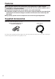
Features ■ 2 ch pre-main amplifier that incorporates Onkyo proprietary VL digital amplifier ■ The DIRECT function that allows you to connect the A-1VL to another amplifier and to use the A-1VL as a power amplifier ■ The PREOUT terminals that can be used for your system expansion ■ Independent toroidal transformer for L/R channels, improves additional sound quality by separating the L/R channel voltages to avoid the L/R channels from interferring with each other ■ High quality speaker terminal components tha
Table of Contents Introduction Important Safety Instructions.......................................................................................................2 Precautions ....................................................................................................................................3 Features..........................................................................................................................................4 Supplied Accessories ...............................
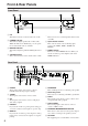
Front & Rear Panels Front Panel 1 POWER button This button is used to set the A-1VL to On or Off. 2 POWER indicator This indicator lights up when the A-1VL is ON. While this indicator is illuminated, you can operate the A-1VL with the remote controller. 3 MUTING indicator This indicator lights up when the Muting function is set. 4 VOLUME control This control is used to set the volume of the A-1VL. 5 Remote control sensor This sensor receives control signals from the remote controller.
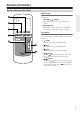
Remote Controller Remote Controller (RC-573A) AMP section Use the following buttons to operate the A-1VL while it is turned on. 1 VOLUME [ / ] buttons These buttons are used to set the volume of the A-1VL. 2 MUTING button This button is used to mute the A-1VL. This function can be set only with the remote controller. CD section Use the following buttons to operate the Onkyo’s CD player with a remote controller signal sensor such as the C-1VL. 3 button This button is used to play CD playback.
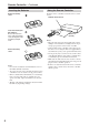
Remote Controller—Continued Inserting the Batteries Detach the battery cover. Using the Remote Controller Point the remote controller toward the remote control sensor. Remote control sensor Insert the two R6 (size AA) batteries. Be sure to match the + and – ends of the batteries to the diagram inside the battery compartment. Attach the battery cover. Notes: • Do not mix new batteries with old batteries. Do not mix different kinds of batteries.
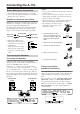
Connecting the A-1VL Before Making Any Connections • Read the manuals supplied with your components. • Don’t connect the power cord until you’ve completed all audio and video connctions. RCA/Phono Connection Color Coding RCA/Phono connections are usually color coded: red and white. Use red plugs to connect right-channel audio inputs and outputs (typically labeled “R”). Use white plugs to connect left-channel audio inputs and outputs (typically labeled “L”).
Connecting the A-1VL—Continued Connecting a Tuner Audio Components Connecting a CD player Use an analog audio cable (RCA/phono) to connect the A-1VL’s CD L/R inputs to the analog audio outputs on your CD player, as shown. Use an analog audio cable (RCA/phono) to connect the A-1VL’s TUNER L/R inputs to the analog audio outputs on your tuner, as shown.
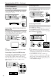
Connecting the A-1VL—Continued Connecting a Power Amplifier Connecting a Preamp You can use the A-1VL as a preamplifier by connecting the A-1VL to a power amplifier. When you use the A-1VL as a preamplifer, connect the main in terminals on the power amplifier to the PREOUT terminals on the A-1VL. You can use the A-1VL as a power amplifier by connecting the A-1VL to a preamplifier.
Enjoying Audio Sources Turning on the A-1VL POWER Press the [POWER] button to turn on the A-1VL. The POWER indicator lights up. Note: It takes about five seconds for the electric circuit to be stable. During this time the A-1VL does not output an audio signal. POWER indicator Tips on sound quality You will get better sound quality 10 to 30 minutes after you turn on the A-1VL. To avoid degrading the sound quality, do not tie audio RCA/phono cables and speaker cables together in a bundle.
Enjoying Audio Sources—Continued Using the DIRECT Function DIRECT You can use the A-1VL as power amplifier by connecting a preamplifier. 1 Press the DIRECT button. ON: The DIRECT function is enabled. When connecting a preamplifier to the A-1VL, the A-1VL will work as a power amplifier. The audio signal from the component connected to the preamplifier will be output. OFF: The audio signal from the component connected to the A-1VL will be output.
Troubleshooting If you have any trouble using your A-1VL, look for a solution in the troubleshooting section. If you can’t resolve the issue yourself, contact your Onkyo dealer. Power Can’t turn on the A-1VL. • Make sure that the power cord is properly plugged into the wall outlet. (page 11) • Unplug the power cord from the wall outlet, wait five seconds or more, then plug the cable in again. The power is turned off and the power indicator blinks in white. • The amp protection circuit has been activated.
Specifications Power Output Dynamic Power THD (Total Harmonic Distortion) Damping Factor Input Sensitivity and Impedance Output Level and Impedance Phono Overload Frequency Response SN Ratio Speaker Impedance Power Supply Power Comsumption Dimensions (W × H × D) Weight Analog Inputs Analog Outputs Pre Outputs Speaker Outputs Front L/R 100 W + 100 W (8 Ω, 1 kHz, DIN) 310 W + 310 W (3 Ω, Front) 240 W + 240 W (4 Ω, Front) 130 W + 130 W (8 Ω, Front) 2 % (Power Rated) / 0.
Sales & Product Planning Div. : 2-1, Nisshin-cho, Neyagawa-shi, OSAKA 572-8540, JAPAN Tel: 072-831-8023 Fax: 072-831-8124 ONKYO U.S.A. CORPORATION 18 Park Way, Upper Saddle River, N.J. 07458, U.S.A. Tel: 201-785-2600 Fax: 201-785-2650 http://www.onkyousa.com ONKYO EUROPE ELECTRONICS GmbH Liegnitzerstrasse 6, 82194 Groebenzell, GERMANY Tel: +49-8142-4401-0 Fax: +49-8142-4401-555 http://www.onkyo.