Contents AV Receiver TX-NR809 Introduction ...................................2 Connections.................................12 Turning On & Basic Operations ......22 Instruction Manual Advanced Operations .................44 Controlling Other Components...70 Appendix ......................................79 Thank you for purchasing an Onkyo AV Receiver. Please read this manual thoroughly before making connections and plugging in the unit.
Introduction WARNING: TO REDUCE THE RISK OF FIRE OR ELECTRIC SHOCK, DO NOT EXPOSE THIS APPARATUS TO RAIN OR MOISTURE. CAUTION: TO REDUCE THE RISK OF ELECTRIC SHOCK, DO NOT REMOVE COVER (OR BACK). NO USER-SERVICEABLE PARTS INSIDE. REFER SERVICING TO QUALIFIED SERVICE PERSONNEL.
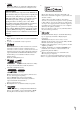
Precautions 1. Recording Copyright—Unless it’s for personal use only, recording copyrighted material is illegal without the permission of the copyright holder. 2. AC Fuse—The AC fuse inside the unit is not userserviceable. If you cannot turn on the unit, contact your Onkyo dealer. 3. Care—Occasionally you should dust the unit all over with a soft cloth. For stubborn stains, use a soft cloth dampened with a weak solution of mild detergent and water. Dry the unit immediately afterwards with a clean cloth.
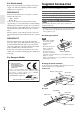
Supplied Accessories For British models Replacement and mounting of an AC plug on the power supply cord of this unit should be performed only by qualified service personnel.
Contents Introduction Important Safety Instructions ......................................... 2 Precautions....................................................................... 3 Supplied Accessories...................................................... 4 Features ............................................................................ 6 Front & Rear Panels......................................................... 8 Front Panel.....................................................................
Features Amplifier Miscellaneous • 135 Watts/Channel @ 8 ohms (FTC) • 180 Watts/Channel @ 6 ohms (IEC) • 230 Watts/Channel @ 6 ohms (JEITA) • WRAT–Wide Range Amplifier Technology (5 Hz to 100 kHz bandwidth) • Linear Optimum Gain Volume Circuitry • 3-Step Inverted Darlington Circuitry • H.C.P.S.
*1 THX and the THX logo are trademarks of THX Ltd. which may be registered in some jurisdictions. All rights reserved. THX Select2 Plus Before any home theater component can be THX Select2 Plus certified, it must pass a rigorous series of quality and performance tests. Only then can a product feature the THX Select2 Plus logo, which is your guarantee that the Home Theater products you purchase will give you superb performance for many years to come.
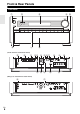
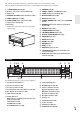
Front & Rear Panels Front Panel a b c f g d e h (North American and Taiwan models) i j k lm n opq u v w (European, Australian and Asian models) z En 8 A x r s y t
The actual front panel has various logos printed on it. They are not shown here for clarity. The page numbers in parentheses show where you can find the main explanation for each item.
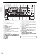
Rear Panel a bc de f o g h p i q a DIGITAL IN COAXIAL and OPTICAL jacks b RS232 port Terminal for control.
Remote Controller Controlling the AV Receiver a i c b c *1 For detailed information, see the pages in parentheses. a 8RECEIVER button (22) *2 j *2 k d d b ACTIVITIES buttons (43, 78) c REMOTE MODE/INPUT SELECTOR buttons (23) d SP LAYOUT button (42) e Arrow q/w/e/r and ENTER buttons f SETUP button (44) g Listening Mode buttons (34) h DIMMER button (40) e a f To control the AV receiver, press RECEIVER to select Receiver mode.
Connections Connecting the AV Receiver Connecting Your Speakers Connecting the Speaker Cables The following illustration shows which speaker should be connected to each pair of terminals. If you’re using only one surround back speaker, connect it to the SURR BACK L terminals.
Speaker Configuration Speaker Connection Precautions The following table indicates the channels you should use depending on the number of speakers that you have. No matter how many speakers you use, a powered subwoofer is recommended for a really powerful and solid bass. To get the best from your surround sound system, you need to set the speaker settings automatically (➔ page 31) or manually (➔ page 47).
Using Dipole Speakers You can use dipole speakers for the surround and surround back speakers. Dipole speakers output the same sound in two directions. Dipole speakers typically have an arrow printed on them to indicate how they should be positioned. The surround dipole speakers (A) should be positioned so that their arrows point toward the TV/screen, while the surround back dipole speakers (B) should be positioned so that their arrows point toward each other, as shown.
Connecting a Power Amplifier If you want to use a more powerful power amplifier, you can use the AV receiver as a preamp. Connect all speaker outputs to the power amplifier. See the manuals supplied with your amplifier for details. Note *1 Specify “None” for any channel that you don’t want to output (➔ page 48).
About AV Connections Connecting AV components : Video & Audio HDMI cable TV, projector, etc. : Video Other cables AV receiver AV receiver Blu-ray Disc/ DVD player Blu-ray Disc/ DVD player Game console TV, projector, etc. • Before making any AV connections, read the manuals supplied with your AV components. • Don’t connect the power cord until you’ve completed and double-checked all AV connections.
Connecting Components with HDMI VCR or DVD recorder/Digital Video Recorder Game console TV, projector, etc. Blu-ray Disc/DVD player Personal computer Satellite/cable set-top box, etc. Camcorder Connect your components to the appropriate jacks. The default input assignments are shown below. ✔: Assignment can be changed (➔ page 46).
Connecting Your Components The on-screen menus appear only on a TV that is connected to the HDMI OUT MAIN. If your TV is connected to other video outputs, use the AV receiver’s display when changing settings.
Connect your components to the appropriate jacks. The default input assignments are shown below. See “Connection Tips and Video Signal Path” for more information (➔ page 88). ✔: Assignment can be changed (➔ page 46). No.
Connecting Onkyo u Components 1 Make sure that each Onkyo component is connected with an analog audio cable (connection H in the hookup examples) (➔ page 18). 2 3 Make the u connection (see the illustration). If you’re using an RI Dock, or cassette tape deck, change the Input Display (➔ page 41).
Connecting the Antennas This section explains how to connect the supplied indoor FM antenna and AM loop antenna. The AV receiver won’t pick up any radio signals without any antenna connected, so you must connect the antenna to use the tuner. North American and Taiwan models Push. Insert wire. Release. European, Australian and Asian models Insert the plug fully into the jack. Assembling the AM loop antenna Insert the plug fully into the jack.
Turning On & Basic Operations Turning On/Off the AV Receiver (North American and Taiwan models) 8ON/STANDBY (European, Australian and Asian models) 8ON/STANDBY 8RECEIVER RECEIVER %POWER Turning On 1 (European, Australian and Asian models) Set %POWER to the ON position (^) on the front panel. The AV receiver enters standby mode. 2 Press 8ON/STANDBY on the front panel. or Press RECEIVER followed by 8RECEIVER on the remote controller. The AV receiver comes on, the display lights.
Playback The on-screen menus appear only on a TV that is connected to the HDMI OUT MAIN. If your TV is connected to other video outputs, use the AV receiver’s display when changing settings. Controlling Contents of USB or Network Devices See “Controlling Other Components” about the operation of other components (➔ page 73). This section describes the procedure for using the remote controller unless otherwise specified. Press USB or NET first.
j MENU This button returns to top menu of the Internet Radio service. k RETURN This button returns to the previous menu. l 6 This button selects the next song. m 4 This button fast-forwards the current song. Playing an iPod/iPhone via USB This section explains how to play music/video files on the iPod/iPhone.
Extended Mode (Music) control The music content information is displayed (lists are displayed), and you can control the music content while looking at the screen. Top screen list: Playlists, Artists, Albums, Genres, Songs, Composers, Shuffle Songs, Now Playing. Extended Mode (Video) control The video content information is displayed (lists are displayed), and you can control the video content while looking at the screen. Top screen list: Movies, Music Videos, TV Shows, Video Podcasts, Rentals.
3 Use q/w to select a program and then press ENTER. Playback starts. My Music 0 : 11 Greate Artist My Favorite Press MENU to enable selection from the following menu items. ` Stations like this: Stations like the one currently being played back are displayed. ` Add to My Favorites: Adds a station to My Favorites list. Press TOP MENU to go to the top menu of the Internet Radio services. Registering My Favorites*1 You can add the currently playing song or station to the “My Favorites”.
Playing Music Files on a Server You need to connect the AV receiver to your home network (➔ page 94). This section explains how to play music files on a computer or media server through the AV receiver (Server Playback). Windows Media Player 11 Setup This section explains how to configure Windows Media Player 11 so that the AV receiver can play the music files stored on your computer. 1 2 Start Windows Media Player 11. 3 Select the “Share my media” check box, and then click “OK”.
Using Remote Playback Listening to AM/FM Radio 1 Start Windows Media Player 12. To enable remote playback, you must first configure Windows Media Player 12. This section describes the procedure using the buttons on the front panel unless otherwise specified. 2 Press NET. The “NET” screen appears. The NET indicator lights. If it flashes, verify the network connection. 3 Use q/w/e/r to select “dlna”, and press ENTER. A list of media server appears.
■ Tuning into stations by frequency You can tune into AM and FM stations directly by entering the appropriate frequency. ■ Deleting Presets 1 Select the preset that you want to delete. See the previous section. 1 2 While holding down MEMORY, press TUNING MODE. The preset is deleted and its number disappears from the display. On the remote controller, press TUNER repeatedly to select “AM” or “FM”, followed by D.TUN. (Actual display depends on the country.
■ Displaying Radio Text (RT) 1 Press RT/PTY/TP once. The RT information scrolls across the display. Note • The message “Waiting” may appear while the AV receiver waits for the RT information. • If the message “No Text Data” appears on the display, no RT information is available.
Using Basic Functions Using the Automatic Speaker Setup With the supplied calibrated microphone, Audyssey MultEQ® XT automatically determines the number of speakers connected, their size for purposes of bass management, optimum crossover frequencies to the subwoofer (if present), and distances from the primary listening position. Audyssey MultEQ XT then removes the distortion caused by room acoustics by capturing room acoustical problems over the listening area in both the frequency and time domain.
3 When you’ve finished making the settings, press ENTER. 9 Use q/w to select an option, and then press ENTER.
Error Messages Changing the Speaker Setup Manually While Audyssey MultEQ® XT Room Correction and Speaker Setup is in progress, one of the error messages below may appear. You can manually make changes to the settings found during Audyssey MultEQ XT Room Correction and Speaker Setup. See also: • “Speaker Configuration” (➔ page 48) • “Speaker Distance” (➔ page 49) • “Level Calibration” (➔ page 49) • “Equalizer Settings” (➔ page 50) MultEQ XT: Auto Setup AUDYSSEY Ambient noise is too high.
Using the Listening Modes Selecting Listening Modes See “About Listening Modes” for detailed information about the listening modes (➔ page 35). ■ Listening Mode Buttons Press RECEIVER first. MUSIC MOVIE/TV GAME THX MOVIE/TV button This button selects the listening modes intended for use with movies and TV. MUSIC button This button selects the listening modes intended for use with music. GAME button This button selects the listening modes intended for use with video games.
About Listening Modes The AV receiver’s listening modes can transform your listening room into a movie theater or concert hall, with high fidelity and stunning surround sound. ■ Explanatory Notes ij ab c kl f SP LAYOUT a b Front speakers c Center speaker d e Surround speakers f Subwoofer(s) g h Surround back speakers i j Front high speakers k l Front wide speakers Listening mode buttons de gh Input Source The following audio formats are supported by the listening mode.
■ Onkyo-Original DSP Listening Modes Listening Mode Description Orchestra Suitable for classical or operatic music, this mode emphasizes the surround channels in order to widen the stereo image, and simulates the natural reverberation of a large hall.
Listening Mode Description Input Source Speaker Layout Dolby Pro Logic IIx*4 Dolby Pro Logic IIx expands any 2-channel source for 7.1-channel playback. It provides a very natural and seamless surround-sound experience Dolby Pro Logic II that fully envelops the listener. As well as music and movies, video games PL Mo v i e can also benefit from the dramatic spatial effects and vivid imaging. If you’re not using any surround back speakers, Dolby Pro Logic II will be S used instead of Dolby Pro Logic IIx.
Listening Mode Description DTS Neo:6 This mode expands any 2-channel source for up to 7.1-channel playback. It uses seven full-bandwidth channels of matrix decoding for matrix-encoded material, providing a very natural and seamless surround sound experience that fully envelops the listener. Ne o : 6 C i n ema Ne o : 6 Mu s i c Ne o : 6 Audyssey DSX*8 Audy s s e y DSX PL Mo v i e DSX PL Mu s i c DSX PL Game 38 Speaker Layout • DTS Neo:6 Cinema S Use this mode with any stereo movie (e.g.
Listening Mode THX S2 C i n ema THX S2 Mu s i c THX S2 Game s THX Su r r EX Description Input Source Speaker Layout • Dolby Pro Logic IIz Height + THX Cinema • Dolby Pro Logic IIz Height + THX Music • Dolby Pro Logic IIz Height + THX Games The combination of Dolby Pro Logic IIz Height and THX Cinema/Music/Games modes can be used. The PLIIz indicator lights on the display.
Using the Home Menu Note *1 The Home menu provides you quick access to frequently used menus without having to go through the long standard menu. This menu enables you to change settings and view the current information. The on-screen menus appear only on a TV that is connected to the HDMI OUT MAIN. If your TV is connected to other video outputs, use the AV receiver’s display when changing settings. 1 Press RECEIVER followed by HOME. The Home menu will be superimposed on the TV screen.
Displaying Source Information You can display various information about the current input source as follows. (Components connected to the UNIVERSAL PORT jack are excluded.) 1 Press RECEIVER followed by DISPLAY repeatedly to cycle through the available information. Tip • Alternatively, you can use the AV receiver’s DISPLAY.
Selecting Speaker Layout You can set which speakers you want to use by priority. 1 Press RECEIVER followed by SP LAYOUT repeatedly to select: ` Speaker Layout:FH: The sound from front high speakers is output by priority. ` Speaker Layout:FW: The sound from front wide speakers is output by priority. ` Speaker Layout:SB: The sound from surround back speakers is output by priority.
Using Easy Macros By using ACTIVITIES in Easy macro mode, you can sequentially operate Onkyo components via simple commands from a single-button press. These commands are user-definable. See “Using Normal Macros” (➔ page 78). 1 Press ACTIVITIES (MY MOVIE, MY TV, or MY MUSIC) to start the Easy macro command. The default sequences of actions are described below. To change the related source component, see “Changing the Source Components” shown later in this chapter.
Advanced Operations Advanced Setup The on-screen menus appear only on a TV that is connected to the HDMI OUT MAIN. If your TV is connected to other video outputs, use the AV receiver’s display when changing settings. Common Procedures in Setup Menu This section describes the procedure for using the remote controller unless otherwise specified. RECEIVER On-screen Setup Menus ENTER q/w/e/r MENU 1. 2. 3. 4. 5. 6. 7. 8. 9.
Changing the “Monitor Out” setting manually Input/Output Assign Main Menu Input/Output Assign 1 Press MONITOR OUT on the front panel. The current setting is displayed. 2 Press MONITOR OUT on the AV receiver repeatedly to select: `HDMI Main, HDMI Sub, Both, Both(Main) or Both(Sub) Monitor Out If you connect your TV to HDMI output, “Monitor Out” setting is automatically set and composite video, S-Video, and component video sources are upconverted* and output.
HDMI Input Note If you connect a video component to an HDMI input, you must assign that input to an input selector. For example, if you connect your Blu-ray Disc/DVD player to HDMI IN 2, you must assign “HDMI2” to the “BD/DVD” input selector. If you’ve connected your TV to the AV receiver with an HDMI cable, composite video, S-video and component video sources can be upconverted* and output by the HDMI output. You can set this for each input selector by selecting the “- - - - -” option.
Digital Audio Input Speaker Setup If you connect a component to a digital audio input, you must assign that input to an input selector. For example, if you connect your CD player to the OPTICAL IN 1, you must assign “OPTICAL1” to the “TV/CD” input selector. Here are the default assignments.
Note Note • If the “Speakers Type(Front)” setting is set to “Bi-Amp”, Powered Zone 2 cannot be used. • When the “Powered Zone 2” setting is set to “Yes”, the surround back, front wide and front high speakers cannot be used. *1 Speaker Configuration *4 This setting is set automatically by Audyssey MultEQ® XT Room Correction and Speaker Setup function (➔ page 31). With these settings, you can specify which speakers are connected and a crossover frequency for each speaker.
■ Wireless Subwoofer When an optional unit is connected to the UNIVERSAL PORT jack on the AV receiver, the speaker setting menu may appear on screen. ` Yes: The audio is output from the speakers connected to the wireless unit. ` No: The audio is not output from the speakers connected to the wireless unit. When the wireless unit is connected to the UNIVERSAL PORT jack on the AV receiver, you can select if you wish to output the audio from the speakers connected to the wireless unit.
Equalizer Settings With the Equalizer settings, you can adjust the tone of speakers individually with a 7-band equalizer. The volume of each speaker can be set (➔ page 49). ■ Equalizer `Manual: You can adjust the equalizer for each speaker manually. Continue with the following procedure: 1 Press w to select “Channel”, and then use e/r to select a speaker. 2 Use q/w to select a frequency, and then use the e/r to adjust the level at that frequency.
Audio Adjust Main menu Audio Adjust With the Audio Adjust functions and settings, you can adjust the sound and listening modes as you like. Multiplex/Mono ■ Multiplex Input Channel ` Main ` Sub ` Main/Sub This setting determines which channel of a stereo multiplex source is output. Use it to select audio channels or languages with multiplex sources, multilingual TV broadcasts, and so on.
■ Dolby Volume `Off `On Dolby Volume automatically adjusts the difference in volume levels which can occur between different contents or source components, freeing the user from having to make volume adjustments. Also, by adjusting the frequency balance according to the playback volume, it recreates the original source audio.
Source Setup Items can be set individually for each input selector. Preparation Press the input selector buttons to select an input source. Main menu Source Setup Audyssey The tone for each speaker is set automatically by Audyssey MultEQ® XT Room Correction and Speaker Setup. To enable the following settings, you must first perform the Room Correction and Speaker Setup (➔ page 31). ■ Audyssey ` Off ` Movie: Select this setting for movie material. The Audyssey indicator lights.
Note • If you want to use Audyssey Dynamic EQ® or Audyssey Dynamic Volume® with THX listening modes, set the “Loudness Plus” setting to “Off” and set “Preserve THX Settings” to “No” (➔ page 50). • If you make Dynamic Volume active, “Dynamic EQ” is set to “On”. The Dynamic Vol indicator will light. • When “Dynamic EQ” is set to “Off”, “Dynamic Volume” is automatically switched to “Off”.
Picture Adjust Name input area BD/DVD 4 - 4. Name Edit Name a n b o 1 { 2 } +10 A N ! [ B O @ ] c p d q e r f s g t h u 3 4 | : Shift 5 6 < 7 > 8 9 0 – ? Space OK Back Space Shift C P # j w CLR D Q $ ; E R % ’ F S ^ , G T & . Shift +10 i v Shift H U I V ( k x l y ` All Erase J W ) K L X Y _ / Space OK Back Space CLR m z Using Picture Adjust, you can adjust the picture quality and reduce any noise appearing on the screen.
With “Picture Mode”, you can change the following settings to be suitable for the movie or game screen by one operation; “Game Mode”, “Film Mode”, “Edge Enhancement”, “Noise Reduction”, “Mosquito NR”, “Random NR”, “Block NR”, “Resolution”, “Brightness”, “Contrast”, “Hue”, “Saturation”, “Color Temperature”, “Gamma”, “Red Brightness”, “Red Contrast”, “Green Brightness”, “Green Contrast”, “Blue Brightness” or “Blue Contrast”.
■ Saturation*1*3*5 ` –50 to 0 to +50 With this setting you can adjust saturation. “–50” is the weakest color. “+50” is the strongest color. ■ Color Temperature*3*5 ` Warm ` Normal ` Cool With this setting you can adjust the color temperature. ■ Gamma*3*5 ` –3 to 0 to +3 Adjust the balance of incoming picture R (red), G (green), and B (blue) color data signal to the output color data signal. ■ Red Brightness*3*5 ` –50 to 0 to +50 With this setting you can adjust the picture red brightness.
■ Fixed Mode `Off: The format is detected automatically. If no digital input signal is present, the corresponding analog input is used instead. `PCM: Only 2-channel PCM format input signals will be heard. If the input signal is not PCM, the PCM indicator will flash and noise may also be produced. `DTS: Only DTS (but not DTS-HD) format input signals will be heard. If the input signal is not DTS, the DTS indicator will flash and there will be no sound.
■ DTS/DTS-ES/DTS-HD With this setting, you can specify the listening mode used when DTS or DTS-HD High Resolution format digital audio signals are played (DVD, LD, CD, etc.). Specifies the default listening mode for DTS-HD Master Audio sources, such as Blu-ray or HD DVD (input via HDMI). ■ Other Multich Source Specifies the default listening mode for multichannel PCM sources from HDMI IN such as DVD-Audio, and DSD multichannel sources such as Super Audio CD.
Multi Zone HDMI ■ Zone 2 Out, Zone 3 Out `Fixed: The Zone 2/3 volume must be set on the amp in that zone. `Variable: The Zone 2/3 volume can be set on the AV receiver. If you’ve connected your Zone 2/3 speakers to an amp with no volume control, set the “Zone 2 Out” and “Zone 3 Out” setting, respectively, to “Variable” so that you can set the volume, balance, and tone of zone 2 and volume of zone 3 on the AV receiver.
Note • Only the input source assigned to the HDMI IN via “HDMI Input” is enabled (➔ page 45). • The power consumption during standby mode will increase during the HDMI Through function; however in the following cases, the power consumption can be saved: – The TV is in standby mode. – You are watching a TV program. • Refer to the connected component’s instruction manual for details. • Depending on the connected component, the correct input source may not be selected with the setting set to “Auto”.
Network After modifying the network settings, you must confirm the changes by executing “Save”. ■ Network Control `Enable `Disable This setting enables or disables control over the network. ■ MAC Address This is the AV receiver’s MAC (Media Access Control) address. This address cannot be changed. • Perform the firmware update only when such an announcement is posted on the Onkyo web site. Visit the Onkyo web site for the latest information. • It takes maximum 60 minutes to complete the firmware update.
Remote Controller Setup Main menu Remote Controller Setup Remote Mode Setup See “Looking up for Remote Control Code” (➔ page 73). Activities Setup Via onscreen menu, you can specify what actions will be taken by the Easy macro command in the Easy macro mode (➔ page 43). First, select the ACTIVITIES (MY MOVIE, MY TV, or MY MUSIC) that you want to configure.
Speaker Levels Audyssey ■ Subwoofer Level `–15.0dB to 0.0dB to +12.0dB in 0.5 dB steps. ■ Audyssey See “Audyssey” in “Source Setup” (➔ page 53). ■ Center Level `–12.0dB to 0.0dB to +12.0dB in 0.5 dB steps. You can adjust the volume of each speaker while listening to an input source. These temporary adjustments are cancelled when the AV receiver is set to standby. To save the setting you made here, go to “Level Calibration” (➔ page 49) before setting the AV receiver to standby.
Music Optimizer ■ Music Optimizer ` Off ` On Turn this setting on to enhance the sound quality of compressed music files. Use it with music files that use “lossy” compression, such as MP3. Note • The Music Optimizer function only works with PCM digital audio input signals with a sampling rate below 48 kHz and analog audio input signals. The Music Optimizer is disabled when the Direct or Pure Audio listening mode is selected. • The setting is stored individually for each input selector. • The M.
Multi Zone In addition to the main listening room, you can also enjoy playback in the other room, or as we call Multi Zone. And, you can select a different source for each room. Connecting the Zone Speakers to an Additional Amplifier Making Multi Zone Connections There are two ways you can connect Zone speakers: 1. Connect them directly to the AV receiver. 2. Connect them to an additional amplifier. Connecting Your Zone 2 Speakers Directly to the AV receiver This setup allows 7.
Controlling Zone 2/3 Components ■ Operating on the AV receiver Input selector buttons ■ Operating on the remote controller To control Zone 2/3, you must press the remote controller’s ZONE first. ZONE turns red while Zone 2 is on, and green while Zone 3 is on. MASTER VOLUME 8RECEIVER ZONE Input selector buttons MUTING ZONE 3 ZONE 2 OFF 1 To turn on Zone 2/3 and select an input source, press ZONE 2 or ZONE 3 followed by an input selector button within 8 seconds.
Adjusting the Volume for Zones ■ Operating on the remote controller 1 2 press ZONE repeatedly. Use VOL q/w to adjust the volume. ■ Operating on the AV receiver 1 Press ZONE 2 or ZONE 3 (the Z2/3 indicator on the display flash). 2 Use MASTER VOLUME control within 8 seconds to adjust the volume. If your Zone 2/3 speakers are connected to a receiver or integrated amp in Zone 2/3, use its volume control to adjust the volume.
Using the Remote Controller in Zone and Multiroom Control Kits To control the AV receiver with the remote controller while you’re in Zone, you’ll need a commercially available multiroom remote control kit for each zone. • Multiroom kits are made by Niles and Xantech. These kits can also be used when there isn’t a clear line of sight to the AV receiver’s remote sensor, such as when it’s installed inside a cabinet.
Controlling Other Components iPod/iPhone Playback via Onkyo Dock Using the Onkyo Dock The Dock is sold separately. Models sold are different depending on the region. For the latest information on the Onkyo Dock components, see the Onkyo web site at: http://www.onkyo.com Before using the Onkyo Dock components, update your iPod/iPhone with the latest software, available from the Apple web site. For supported iPod/iPhone models, see the instruction manual of the Onkyo Dock.
■ Status Messages If either of the following messages is not displayed on the AV receiver’s display, check the connection to your iPod/iPhone. • PORT Reading The AV receiver is checking the connection with the dock. • PORT Not Support The AV receiver do not support the connected dock. • PORT UP-A1 UP-A1 Dock is connected. Note • The AV receiver displays the message “UP-A1” for several seconds after recognizing the UP-A1.
✔: Available buttons Press the appropriate REMOTE MODE first. Buttons ✔ a 8SOURCE*1 b TOP ✔*3 ✔ ✔*4 ✔ d 1, 3, 2, 5, 4, 7, 6 ✔ ✔ e REPEAT RANDOM ✔ ✔ ✔ ✔ f DISPLAY g MUTING ✔*5 ✔*6 ✔ ✔ h ALBUM +/– ✔*4 ✔ i VOL q/w ✔ ✔ j MENU k RETURN ✔ l MODE ✔*7 PLAYLIST e/r i b j c k ✔ MENU*2 c q/w/e/r, ENTER g h u Dock f UP-A1 Dock a Onkyo Dock ✔ ✔*8 d e l • With some iPod/iPhone models, generations and RI Docks, certain buttons may not work as expected.
Controlling Other Components You can use the AV receiver’s remote controller to control your other AV components, including those made by other manufacturers. This section explains how to enter the remote control code (with the default underlined) for a component that you want to control: DVD, TV, CD, etc. “Learning Commands” for learning commands directly from another component’s remote controller (➔ page 77).
12 When you searched for the model, a message “Successful” will appear. Now the transfer is successful! Go to step 15. When you did NOT search for the model, the following screen appears. Push any key (except for arrow buttons and ENTER) to see if the component responds. Entering Remote Control Codes You’ll need to enter a code for each component that you want to control. 1 Look up the appropriate remote control code in the separate Remote Control Codes list. The codes are organized by category (e.g.
Remote Control Codes for Onkyo Components Connected via u 2 Onkyo components that are connected via u are controlled by pointing the remote controller at the AV receiver, not the component. This allows you to control components that are out of view, in a rack, for example. 1 2 3 Make sure the Onkyo component is connected with an u cable and an analog audio cable (RCA). See “Connecting Onkyo u Components” for details (➔ page 20).
✔: Available buttons Press the appropriate REMOTE MODE first.
Learning Commands Note The AV receiver’s remote controller can learn the commands of other remote controllers. By transmitting, for example, the Play command from your CD player’s remote controller, the supplied remote controller can learn it, and then reproduce the exact same command when its 1 is pressed in CD remote mode. This is useful when you’ve entered the appropriate remote control code (➔ page 74) but some buttons don’t work as expected.
Running Macros Using Normal Macros You can program the remote controller’s ACTIVITIES to perform a sequence of remote control actions. Example: To play a CD you typically need to perform the following actions: 1. Press RECEIVER to select the Receiver remote controller mode. 2. Press 8RECEIVER to turn on the AV receiver. 3. Press TV/CD to select the TV/CD input source. 4. Press 1 to start playback on the CD player. You can program ACTIVITIES so that all four actions are performed with just one button press.
Appendix Troubleshooting If you have any trouble using the AV receiver, look for a solution in this section. If you can’t resolve the issue yourself, contact your Onkyo dealer. If you can’t resolve the issue yourself, try resetting the AV receiver before contacting your Onkyo dealer. To reset the AV receiver to its factory defaults, turn it on and, while holding down VCR/DVR, press 8ON/STANDBY. “Clear” will appear on the display and the AV receiver will enter standby mode.
■ Only the front speakers produce sound When the Stereo or Mono listening mode is selected, — only the front speakers and subwoofer produce sound. In the Mono listening mode, only the front speakers 51 output sound if the “Output Speaker” setting is set to “Left / Right”. Check the Speaker Configuration. 48 ■ Only the center speaker produces sound In the Mono listening mode, only the center speaker 51 output sound if the “Output Speaker” setting is set to “Center”.
Playing DTS program material, using the pause, fast — forward, or fast reverse function on your player may produce a short audible noise. This is not a malfunction. ■ The beginning of audio received by an HDMI IN can’t be heard Since it takes longer to identify the format of an HDMI signal than it does for other digital audio signals, audio output may not start immediately. — ■ There’s no sound during Whole House Mode Make sure you’ve selected an analog audio input.
For a proper operation of the remote controller as a 41 cassette tape deck is connected to the TV/CD IN jack, or as an RI Dock is connected to the TV/CD IN, VCR/DVR IN or GAME IN jacks, you must set the input display accordingly. If you cannot operate it, you will need to enter the appropriate remote control code. 73 To control another manufacturer’s component, point 74 the remote controller at that component.
Check the “Network” settings. 62 ■ Playback stops while listening to music files on the server Make sure your server is compatible with the AV receiver. 94, 96 If you download or copy large files on your — computer, playback may be interrupted. Try closing any unused programs, use a more powerful computer, or use a dedicated server. If the server is serving large music files to several — networked devices simultaneously, the network may become overloaded and playback may be interrupted.
■ If the picture on your TV/monitor connected to the HDMI output(s) is unstable, try switching the DeepColor function off To turn off the DeepColor function, simultaneously press the CBL/SAT and 8ON/STANDBY buttons on the AV receiver. While holding down CBL/SAT, press 8ON/STANDBY until “Off” appears on the display. Then, release both buttons. To reactivate the DeepColor function, repeat the above process until “On” appears on the display and release the buttons.
Firmware Update To update the firmware of the AV receiver, you can choose from the following two methods: update via network, or update via USB storage. Choose the one that best suits your environment. Before proceeding with the update, please read the corresponding explanations carefully. ■ Update via network You need a wired Internet connection to update the firmware. ■ Update via USB storage (➔ page 86) Please prepare a USB storage device such as a USB flash memory stick.
7 Using 8ON/STANDBY on the front panel, turn off and on the AV receiver. Do not use 8RECEIVER on the remote controller. Congratulations! You now have the latest firmware installed on your Onkyo AV receiver. Troubleshooting Case 1: If “No Update” is displayed on the front display of the AV receiver, it means that the firmware has already been updated. You do not need to do anything further. Case 2: If an error occurs, “Error!! *-** No media” is displayed on the front display of the AV receiver.
7 8 9 10 11 12 13 Press RECEIVER followed by SETUP on the remote controller. The setup menu will be displayed on the TV screen. The procedures thereafter can also be performed on the AV receiver by using its SETUP, arrow and ENTER buttons. Troubleshooting Select “Hardware Setup” and press ENTER. Case 2: If an error occurs, “Error!! *-** No media” is displayed on the front display of the AV receiver. (Alpha-numeric characters on the front display are denoted by asterisks.
Connection Tips and Video Signal Path The AV receiver supports several connection formats for compatibility with a wide range of AV equipment. The format you choose will depend on the formats supported by your components. Use the following sections as a guide. The on-screen menus appear only on a TV that is connected to the HDMI OUT MAIN. If your TV is connected to other video outputs, use the AV receiver’s display when changing settings.
Audio Connection Formats Audio components can be connected by using any of the following audio connection formats: analog, analog multichannel, optical, coaxial or HDMI. When choosing a connection format, bear in mind that the AV receiver does not convert digital input signals for analog line outputs and vice versa. For example, audio signals connected to an optical or coaxial digital input are not output by the analog VCR/DVR OUT. Audio Signal Flow Chart Blu-ray Disc/DVD player, etc.
Video Resolution Chart The following tables show how video signals at different resolutions are output by the AV receiver.
Using an RIHD-compatible TV, Player, or Recorder p, which stands for Remote Interactive over HDMI, is the name of the system control function found on Onkyo components. The AV receiver can be used with CEC (Consumer Electronics Control), which allows system control over HDMI and is part of the HDMI standard. CEC provides interoperability between various components, however, operation with components other than p-compatible components cannot be guaranteed.
■ How to connect and setup 1 3 Confirm the connecting and setting. 1. Connect the HDMI OUT MAIN jack to the HDMI input jack of the TV. Blu-ray Disc/DVD player, etc. HDMI connection AV receiver DIGITAL AUDIO connection (OPTICAL) HDMI connection TV, projector, etc. 2. Connect the audio output from the TV to the OPTICAL IN 2 jack of the AV receiver using an optical digital cable.
About HDMI Designed to meet the increased demands of digital TV, HDMI (High Definition Multimedia Interface) is a new digital interface standard for connecting TVs, projectors, Blu-ray Disc/DVD players, set-top boxes, and other video components. Until now, several separate video and audio cables have been required to connect AV components.
Network/USB Features Connecting to the Network Network Requirements The following diagram shows how you can connect the AV receiver to your home network. In this example, it’s connected to a LAN port on a router, which has a 4-port 100Base-TX switch built-in. Internet radio Modem WAN LAN Computer or media server Router ■ Ethernet Network For the best results, a 100Base-TX switched Ethernet network is recommended.
Server Requirements ■ Server playback The AV receiver can play digital music files stored on a computer or media server and supports the following technologies: • Windows Media Player 11 • Windows Media Player 12 • Windows Media Connect 2.0 • DLNA-certified media server If the operating system of your computer is Windows Vista, Windows Media Player 11 is already installed. Windows Media Player 11 for Windows XP can be downloaded for free from the Microsoft web site.
Supported Audio File Formats For server playback and playback from a USB device, the AV receiver supports the following music file formats. Variable bit-rate (VBR) files are supported. However, playback time may not be display correctly. ■ LPCM (Linear PCM) • Sampling rates of 8 kHz, 11.025 kHz, 12 kHz, 16 kHz, 22.05 kHz, 24 kHz, 32 kHz, 44.1 kHz, 48 kHz, 64 kHz, 88.2 kHz, and 96 kHz are supported. • Quantization bit: 8 bit, 16 bit, 24 bit * Only for playback via network.
Specifications Amplifier Section Tuner Section Rated Output Power All channels: FM Tuning Frequency Range (North American) 87.5 MHz - 107.9 MHz (Others) 87.5 MHz - 108.0 MHz, RDS AM Tuning Frequency Range 522/530 kHz - 1611/1710 kHz Preset Channel 40 (North American) 135 watts minimum continuous power per channel, 8 ohm loads, 2 channels driven from 20 Hz to 20 kHz, with a maximum total harmonic distortion of 0.
■ Audio Outputs Analog VCR/DVR, PRE OUT, ZONE2 PRE/LINE OUT, ZONE3 PRE/LINE OUT Analog Multichannel Pre Outputs 7 Subwoofer Pre Outputs 2 Speaker Outputs Main (L, R, C, SL, SR, SBL, SBR) + Front Wide/ZONE2 (L, R) + Front High (L, R) Phones 1 (6.3 ø) ■ Others Setup Mic RS232 Universal Port RI USB Ethernet IR Input IR Output 12 V Trigger Out 1 1 1 1 1 (Front)/1 (Rear) 1 1 1 2 Specifications and features are subject to change without notice.
Memo En 99
2-1, Nisshin-cho, Neyagawa-shi, OSAKA 572-8540, JAPAN Tel: 072-831-8023 Fax: 072-831-8163 http://www.onkyo.com/ 18 Park Way, Upper Saddle River, N.J. 07458, U.S.A. Tel: 800-229-1687, 201-785-2600 Fax: 201-785-2650 http://www.us.onkyo.com/ Liegnitzerstrasse 6, 82194 Groebenzell, GERMANY Tel: +49-8142-4401-0 Fax: +49-8142-4401-555 http://www.eu.onkyo.