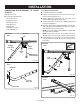
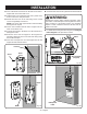
INSTALLATION CONNECTING DOOR BRACKET TO OUTER TROLLEY To connect sectional doors: Lower the garage door completely. See Figures 44 - 49. Locate the following items: Pull the emergency release rope down and slide outer trolley toward the garage door. Secure straight door arm to the rear of the outer trolley using medium clevis pin and hitch pin. Curved Door Arm Straight Door Arm Secure curved door arm to the door bracket using small clevis pin and hitch pin.
INSTALLATION To connect single-panel doors: Lower the garage door completely. Pull the emergency release rope down and slide outer trolley toward the garage door. Place the curved and straight arms together and align the holes. Choose two sets of aligned holes and install bolts and nuts. Tighten bolts and nuts with a 13 mm socket. WARNING: DO NOT operate the garage door opener unless the safety sensors are installed and working correctly.
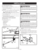
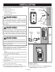
INSTALLATION NOTE: The top of the sensor should be between four and six inches above the floor. NOTE: The receiving sensor has a green LED. Ensure that the lens on this sensor is not exposed to direct sunlight. Mark the position of the hole in the bracket. Secure brackets in place using nails or drill 3/16 in. pilot holes and secure with lag screws. Tighten screws with an 11 mm socket.
INSTALLATION Twist the white wires from both sensors together and insert them into the left terminal marked with W. For alignment instructions, see Aligning The Safety Sensors in the Operations section. Wires (Striped) WARNING: Make sure the keypad is mounted high enough to prevent unauthorized activation of the garage door opener. It should be placed at least five feet above the floor so that it is inaccessible to children.
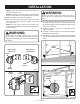
INSTALLATION Insert a flat head screwdriver into the tabs on the indoor keypad and remove the back cover. Insert the white wire into the right terminal marked with W. Hold the back cover against the wall. Use a pencil and a level to mark screw hole placement. Mount the back cover to the wall using screws. Install screws using Phillips screwdriver. NOTE: Use screws and drywall anchors when installing the keypad into drywall.
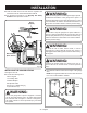
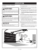
INSTALLATION INSTALLING THE OUTDOOR KEYPAD See Figures 61 - 63. Locate the following items: Outdoor Keypad Outdoor Keypad Pencil Screws (1 in., Phillips Hd.) [2] Drywall Anchors (2) WARNING: Key Hole Do not use garage door opener if keypads or remotes do not start and stop the motor. An opener that cannot be controlled with a keypad or remote is dangerous, can result in death or serious personal injury, and must be repaired. Screwdriver Top Screw Fig.
OPERATION IMPORTANT SAFETY INSTRUCTIONS WARNING: TO REDUCE THE RISK OF SEVERE INJURY OR DEATH: WARNING: Do not allow familiarity with products to make you careless. Remember that a careless fraction of a second is sufficient to cause death or serious injury. WARNING: Do not use any attachments or accessories not recommended by the manufacturer of this product. The use of attachments or accessories not recommended can result in serious death or personal injury. 1. READ AND FOLLOW ALL INSTRUCTIONS. 2.
OPERATION CONNECTING THE GARAGE DOOR OPENER TO A POWER SUPPLY See Figures 64 and 65. For AC power: Assemble and mount the garage door opener as described earlier in the Installation section. Connect the garage door opener to an AC power supply. NOTE: Make sure the power supply is normal household voltage, 120 volts, AC only, 60 Hz. Ensure that the power cord does not droop excessively or contact moving parts. For DC power: Unplug the garage door opener.
OPERATION INSTALLING MODULES See Figures 66 and 67. The garage door opener can power a variety of AC and DC modules. For a complete list of modules, visit www.ryobitools.com. NOTE: If the garage door opener is unplugged and a charged battery pack is installed, the AC receptacles and DC module ports will be disabled but the sensors and LED lights will continue to function normally. Hooks WARNING: Use only recommended accessories listed on our website, in this manual, or in addendums.
OPERATION Install and wire the safety sensors as described earlier in the Installation section. ALIGNING THE SAFETY SENSORS See Figure 68. Connect the garage door opener to an AC power supply. NOTE: Make sure the power supply is normal household voltage, 120 volts, AC only, 60 Hz WARNING: DO NOT operate the garage door opener unless the safety sensors are installed and working correctly.
OPERATION SAFETY SENSOR DIAGNOSTIC FEEDBACK LED FUNCTIONS RED LED (TRANSMITTER) GREEN LED (RECEIVER) ON ON PROBLEM No problem indicated SOLUTION No action required Power head is unplugged or the battery Connect to power supply or charge is depleted the battery pack Wires from power head may be Replace damaged or broken wires damaged OFF OFF Wires not connected Connect wires to power head Wires connected to the wrong terminal Connect wires to the correct terminal One or both sensors are defective
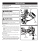
OPERATION SETTING THE DOOR TRAVEL LIMITS See Figures 69 - 76. DANGER: Ensure that the safety sensors are installed and working properly. Without the proper safety devices in place, a closing garage door could kill or seriously injure someone in its path. The console on your garage door opener makes it easy to set the open and close positions of your door. The opener will automically sense the weight of your door and provide the force required to open and close it.
OPERATION NOTICE: Do not open or close the garage door using the indoor keypad or remotes until the travel limits have been properly set. Doing so could cause severe damage to the garage door or the garage door opener. Correct (Fully Open Position) Before setting the travel limit: Pull the emergency release rope down and manually open the garage door until the outer trolley engages the inner trolley. Once you begin setting the travel limits, you have two minutes to complete each step.
OPERATION To set the travel limit for the closed position: Press and hold the DOWN button for three seconds. After you release the button, it will begin blinking and continue blinking until the travel limit has been set. Set Press and hold the DOWN button to move the garage door to the closed position. Down Up For fine adjustments, press and release the UP or DOWN buttons. Once the door is in the closed position, press the SET button to program the travel limit.
OPERATION USING THE INDOOR KEYPAD can only be controlled using the indoor keypad and smart phone. The unit will not respond to car remotes or the outdoor keypad. See Figure 77. NOTE: The LEDs in the indoor keypad will blink when the unit is in vacation mode. WARNING: Keep moving door in sight when using indoor keypad. Contact with moving door can cause DEATH or serious injury. The indoor keypad has backlights that turn on when garage door opener is connected to a power supply.
OPERATION TESTING THE AUTOMATIC REVERSAL SYSTEM See Figure 78. Press and release the UP/DOWN button on the indoor keypad to raise the garage door. Place a 1-1/2 in. board (approx. the size of a 2x4 laid flat) on the garage floor beneath the door. Press and release the UP/DOWN button on the indoor keypad to lower the garage door. When the door strikes the board, it should reverse direction immediately.
OPERATION PROGRAMMING THE OUTDOOR KEYPAD See Figures 79 - 80. WARNING: Program Keep moving door in sight when using outdoor keypad. Contact with moving door can cause DEATH or serious injury. Once you begin programming the outdoor keypad, you have two minutes to complete each step. If a step is not completed within two minutes, programming information will be erased. If you haven’t already done so, install a 9-volt battery into the outdoor keypad.
OPERATION PROGRAMMING THE CAR REMOTES Visor Clip See Figure 81. WARNING: Car Remote Keep moving door in sight when using car remotes. Contact with moving door can cause DEATH or serious injury. Once you begin programming the car remotes, you have two minutes to complete each step. If a step is not completed within two minutes, programming information will be erased. Press the PROGRAM button on the garage door opener’s console.
MAINTENANCE IMPORTANT SAFETY INSTRUCTIONS WARNING: TO REDUCE THE RISK OF SEVERE INJURY OR DEATH: WARNING: Before inspecting, cleaning or servicing the machine, lower the garage door, shut off motor, wait for all moving parts to stop, disconnect unit from power supply, and remove all modules. Failure to follow these instructions can result in serious personal injury or property damage. WARNING: When servicing, use only identical replacement parts.
MAINTENANCE REPLACING CAR REMOTE BATTERIES Snap the sections together to close. See Figure 83. Make sure the remote is securely reassembled before attaching the visor clip. WARNING: KEEP OUT OF REACH OF CHILDREN. Swallowing batteries may lead to serious injury or death. Coin Visor Clip WARNING: Risk of injury due to fire, explosion, or leakage. Do not disassemble, charge, crush, or expose to fire or high temperatures. Remove visor clip.
ACCESSORIES The following accessories are not included with your garage door opener but may be available where you purchased this product. For assistance call 1-877-205-5714. 8 ft. Extension Kit..............................................................................................................................................GDAEXT100 Bluetooth Speaker.................................................................................................................................................
TROUBLESHOOTING PROBLEM All of the console buttons are blinking continuously POSSIBLE CAUSE SOLUTION DC voltage below 24V. Disconnect the unit from the power supply. Wait several minutes before reconnecting. If problem persists, contact customer service. DC voltage exceeds 40 volts Disconnect the unit from the power supply. Wait several minutes before reconnecting. If problem persists, contact customer service.
TROUBLESHOOTING PROBLEM POSSIBLE CAUSE SOLUTION Garage door opener is in the fully open position and cannot be closed with a car remote, smart phone, or keypad The safety sensors are not receiving power. Inspect sensor wires for damage and ensure they are installed correctly. Reset travel limits.
WARRANTY LIMITED WARRANTY STATEMENT One World Technologies, Inc., warrants to the original retail purchaser that this RYOBI™ brand garage door opener is free from defect in material and workmanship and agrees to repair or replace, at One World Technologies, Inc.’s discretion, any defective product free of charge within these time periods from the date of purchase.
FCC COMPLIANCE The following FCC compliance information is for the GD200 garage door opener only. For information regarding other products, like modules and accessories, refer to the labels and documentation included with those items. WARNING: Changes or modifications to this unit not expressly approved by the party responsible for compliance could void the user’s authority to operate the equipment. This device complies with part 15 of the FCC rules.
This equipment complies with FCC RF radiation exposure limits set forth for an uncontrolled environment. This equipment should be installed and operated with minimum distance of 20 cm between thThis equipment complies with FCC RF radiation exposure limits set forth for an uncontrolled environment. This equipment should be installed and operated with minimum distance of 20 cm between the radiator and your body.e radiator and your body.