
User's Manual

NOTE: After making sure that all safety warnings and precautions (pages 2-4) are
adhered to, the Fence Control is ready to be turned ON.
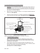
2. When the Battery (part #10) is fully charged, place the Switch Cover (#13) on the
Power Switch (#5) and turn the Power Switch (part #5) to its “ON” position. (See
Figure C, and Assy. Diagram.)
3. Observe the Indicating Lamp (part #7). A blinking Indicating Lamp shows that the
electrical output is working properly. The fence is now electrically activated.
(See Figure C, and Assy. Diagram.)
4. NOTE: If the Indicating Lamp does not blink, turn the Power Switch (part #5)
to its “OFF” position. Have a qualified, certified electrician disconnect both 12
Gauge Insulated Wires from the Fence Control. Then, turn the Power Switch to
its “ON” position. If the Indicating Lamp does blink, the problem is with the fence.
If the Indicating Lamp does not blink, the problem is with the Fence Control or its
Battery (part #10). (See Figures B, C, and Assy. Diagram.)
RECOMMENDED ASSOCIATED ELECTRIC FENCE PRODUCTS
1. CAUTION: For personal safety, it is recommended that only a qualified, certified,
electrician install electrical products.
Posts:
1. Use posts made of treated wood, steel, aluminum, or fiberglass.
Fence Wire:
1. Use size 20 through 9 American wire gauge. Use a smooth, galvanized steel
electric fence wire. Or use an aluminum wire which conducts electricity four
times better than steel. Or in certain cases, use a plastic/metallic wire according
to the manufacturer’s recommendations.
Insulated Wire:
1. Use size 12 Gauge for running under roads and under gates. If desired, use
insulated wire with PVC tubing.
Insulators:
1. Use standard Fi-Shock insulators on rod-type line support posts, or on wooden
posts. At the starting point, and at fence corners, use Fi-Shock corner post
insulators. Always insulate wooden posts. Do not staple fence wire directly to the
post.
SKU 47454 PAGE 8