
User's Manual

To Connect The Fence Line To The Fence Control:
1. CAUTION: Prior to connecting the Fence Line to the Fence Control, make sure
its Power Switch (part #5) is in the “OFF” position (the Switch Cover [#13] must
be removed from the Power Switch when the Fence Control is not in operation).
(See Figure C, and Assy. Diagram.)
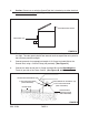
2. Splice one end of an appropriate length of 12-1/2 Gauge Insulated Wire onto the
Fence Line. (See Figure B.)
3. Connect the other end of the 12-1/2 Gauge Insulated Wire to the Red/Positive
Terminal (part #6) of the Fence Control. (See Figures B, and C.)
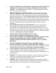
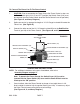
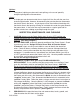
ANGLE
ADJUSTING FRAME
(#3)
SOLAR PANEL (#2)
BLACK/NEGATIVE TERMINAL (#6)
INDICATING LAMP (#7)
RED/POSITIVE WIRE
BLACK/NEGATIVE WIRE
MAIN BODY (#4)
BATTERY (#10)
RED/POSITIVE TERMINAL (#6)
POWER SWITCH (#5)
BATTERY COMPARTMENT
DOOR (#11)
SCREW (#12)
FIGURE C
OPERATING INSTRUCTIONS
NOTE: For additional references to the parts listed below, refer to the
Assembly Diagram on page 11.
Note: To operate the Fence Control, the Switch Cover (#13) must be
inserted into the Power Switch (#5) cover and the Power Switch must be
lifted up to the “ON” position.
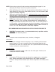
1. Once installed, allow the Fence Control to charge at least eight hours in full,
direct sunlight in order to fully charge the Battery (part #10). If necessary, adjust
the Solar Panel to increase the pickup of solar energy.
(See Figures A, C, and Assy. Diagram.)
SKU 47454 PAGE 7
SWITCH COVER (#13)