
User's Manual
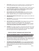
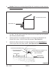

3. Caution: Do not use an existing Ground Rod that is hooked up to other electrical
systems or to a water pipe. (See Figure B.)
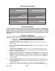
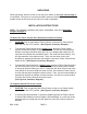
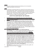
MAIN BODY (#4)
MOUNTING HOLES
FIGURE A
4. The front side of the solar shock (with terminals and switch/key) should face the
sun light. The solar panel should face towards south to expose the solar panel to
the maximum possible sunlight.
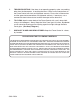
5. Connect one end of an appropriate length of 12 Gauge Insulated Wire to the
Ground Rod, using a Ground Clamp (not provided). (See Figure B.)
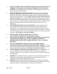
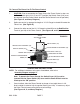
6. Connect the other end of the 12 Gauge Insulated Wire to the Black/Negative
Terminal (part #6) of the Fence Control. (See Figures B, and C.)
RED/POSITIVE TERMINAL (#6)
BLACK/NEGATIVE TERMINAL (#6)
12 GA. INSULATED WIRE
FENCE WIRE
12 GA. INSULATED WIRE
GROUND ROD
GROUND CLAMP
(NOT PROVIDED)
FIGURE B
SKU 47454 PAGE 6
(NOT PROVIDED)
(NOT PROVIDED)