Airlink BCP User and Installation Guide Document Version 1.5 September 2022 Warning: Never power on an Airlink BCP without a load on the RF connector. Ondas Networks Inc. | 165 Gibraltar Court, Sunnyvale, CA 94089 | (888) 350-9994 | ondas.
Table of Contents 1 FCC Compliance .................................................................................................................................... 3 2 FCC Exposure Statement ....................................................................................................................... 3 3 ISED Canada .......................................................................................................................................... 4 3.1 Statement ....................
1 FCC Compliance This device complies with part 15 of the FCC Rules. Operation is subject to the following two conditions: 1. This device may not cause harmful interference, and 2. This device must accept any interference received, including interference that may cause undesired operation. Changes or modifications not expressly approved by Ondas Networks could void the user’s authority to operate the equipment.
3 ISED Canada 3.1 Statement This device complies with Innovation, Science and Economic Development Canada’s license-exempt RSSs. Operation is subject to the following two conditions: 1. This device may not cause interference; and 2. This device must accept any interference, including interference that may cause undesired operation of the device. Cet appareil est conforme aux flux RSS exemptés de licence d'Innovation, Science et Développement économique Canada.
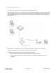
4 System Overview The Airlink BCP platform employs Ondas Networks’ FullMAX technology. The Airlink BCP makes up a computer room communications package, including the radio and associated software/hardware that enables the transmission of ATCS datagrams from the WCPS and WIU to the CC/FEP and vice-versa. It will function as per the standards that are defined in S-9553.V1.0 & S- 9553A.V1.0 Figure 1 System Overview Airlink BCPs will interoperate with the existing Siemens WCP infrastructure.
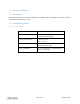
5 Physical Installation 5.1 Introduction An Airlink BCP radio is comprised of software and hardware which is packaged in an indoor enclosure intended for mounting in a 19” rack. 5.2 Airlink BCP Enclosure 5.2.1 Specifications Enclosure Material Dimensions (W x D x H) Aluminum Alloy 19” x 3.
5.2.
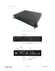
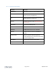
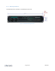
5.2.3 Connection Descriptions Connector Application GPS Antenna SMA female connector for optional GPS antenna. RF Out 50Ω N-Type female connector for RF output to Duplexer Transmit port (High Pass) RF In 50Ω N-Type female connector for RF input from Duplexer Receive port (Low Pass) DC Input DC power input 36 to 75 VDC.
5.2.4 Mounting Guidelines The Airlink BCP can be mounted in a standard built 19 inch rack.
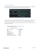
6 System Operation An Airlink BCP radio automatically starts operation when the DC power is connected. The unit conducts a series of self-tests, the results of which are shown on the front panel display module. Figure 1 : Pushbuttons and Display Status information can be accessed using the “Select” and “Enter” pushbuttons to scroll through and select various aspects of the system. The information is shown on the front panel display module.