
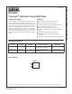
Data Sheet

2
www.fairchildsemi.com
NC7WZ02 TinyLogic
®
UHS Dual 2-Input NOR Gate
NC7WZ02 Rev. 1.0.0
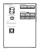
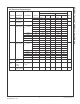
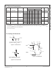
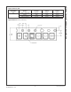
Connection Diagrams Pin Descriptions
Function Table
Y = A + B
H = HIGH Logic Level L = LOW Logic Level
7
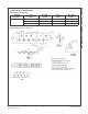
Pad Assignments for MicroPak
(Top Through View)
Pin Assignment for US8
(Top View)
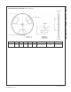
US8 Pin One Orientation Diagram
6 5
4
8
2
V
CC
1
3
GND
A
1
A
1
A
2
B
2
Y
1
V
CC
B
1
Y
2
GND
B
1
Y
2
Y
1
B
2
A
2
1
AAA represents Product Code Top Mark – see
ordering code
Note: Orientation of Top Mark determines Pin One
location. Read the top product code mark left to
right, Pin One is the lower left pin (see diagram).
2
3
4
8
7
6
5
AAA
Pin One
(Top View)
Pin Name Description
A
n
, B
n
Inputs
Y
n
Outputs
Inputs Outputs
ABY
LLH
LHL
HLL
HHL