
Data Sheet


3 www.fairchildsemi.com
NC7S04
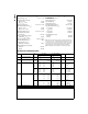
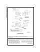
AC Electrical Characteristics
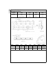
Note 3: C
PD
is defined as the value of the internal equivalent capacitance which is derived from dynamic operating current consumption (I
CCD
) at no output
loading and operating at 50% duty cycle. (See Figure 2.) C
PD
is related to I
CCD
dynamic operating current by the expression:
I
CCD
= (C
PD
) (V
CC
) (f
IN
) + (I
CC
static).
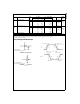
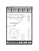
AC Loading and Waveforms
C
L
includes load and stray capacitance
Input PRR = 1.0 MHz, t
w
= 500 ns
FIGURE 1. AC Test Circuit
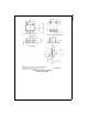
Input = AC Waveforms;
PRR = Variable; Duty Cycle = 50%
FIGURE 2. I
CCD
Test Circuit
FIGURE 3. AC Waveforms
Symbol Parameter
V
CC
T
A
= +25°CT
A
= −40°C to +85°C
Units Conditions
Figure
(V) Min Typ Max Min Max Number
t
PLH
, Propagation Delay 5.0 3.0 15.0 ns C
L
= 15 pF
Figures
1, 3
t
PHL
2.0 18.0 100.0 125.0
ns C
L
= 50 pF
3.0 10.0 27.0 35.0
4.5 7.0 20.0 25.0
6.0 6.0 17.0 21.0
t
TLH
, Output Transition Time 5.0 3.0 10.0 ns C
L
= 15 pF
Figures
1, 3
t
THL
2.0 25.0 125.0 155.0
ns C
L
= 50 pF
3.0 16.0 35.0 45.0
4.5 11.0 25.0 31.0
6.0 9.0 21.0 26.0
C
IN
Input Capacitance Open 2.0 10.0 10.0 pF
C
PD
Power Dissipation Capacitance 5.0 6.0 pF (Note 3) Figure 2