
Data Sheet
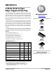

MM74HC574
www.onsemi.com
3
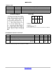
DC ELECTRICAL CHARACTERISTICS (Note 3)
Symbol
Parameter Conditions V
CC
T
A
= 255C T
A
= −40 to 855C T
A
= −55 to 1255C
Units
Typ Guaranteed Limits
V
IH
Minimum HIGH Lev-
el Input Voltage
2.0 V
4.5 V
6.0 V
1.5
3.15
4.2
1.5
3.15
4.2
1.5
3.15
4.2
V
V
IL
Maximum LOW Lev-
el Input Voltage
2.0 V
4.5 V
6.0 V
0.5
1.35
1.8
0.5
1.35
1.8
0.5
1.35
1.8
V
V
OH
Minimum HIGH Lev
-
el Output Voltage
V
IN
= V
IH
or V
IL
⎮I
OUT
⎜ ≤ 20 mA
2.0 V
4.5 V
6.0 V
2.0
4.5
6.0
1.9
4.4
5.9
1.9
4.4
5.9
1.9
4.4
5.9
V
V
IN
= V
IH
or V
IL
⎮I
OUT
⎜ ≤ 6.0 mA
⎮I
OUT
⎜ ≤ 7.8 mA
4.5 V
6.0 V
4.2
5.7
3.98
5.48
3.84
5.34
3.7
5.2
V
V
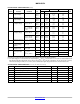
OL
Maximum LOW Lev
-
el Output Voltage
V
IN
= V
IH
or V
IL
⎮I
OUT
⎜ ≤ 20 mA
2.0 V
4.5 V
6.0 V
0
0
0
0.1
0.1
0.1
0.1
0.1
0.1
0.1
0.1
0.1
V
V
IN
= V
IH
or V
IL
⎮I
OUT
⎜ ≤ 6.0 mA
⎮I
OUT
⎜ ≤ 7.8 mA
4.5 V
6.0 V
0.2
0.2
0.26
0.26
0.33
0.33
0.4
0.4
V
I
IN
Maximum Input Cur-
rent
V
IN
= V
CC
or GND 6.0 V ±0.1 ±1.0 ±1.0
mA
I
OZ
Maximum 3−STATE
Output Leakage
Current
V
OUT
= V
CC
or GND
OC = V
IH
6.0 V ±0.5 ±5.0 ±10
mA
I
CC
Maximum Quiescent
Supply Current
V
IN
= V
CC
or GND
I
OUT
= 0 mA
6.0 V 8.0 80 160
mA
DI
CC
Quiescent Supply
Current per Input
Pin
V
CC
= 5.5 V
V
IN
= 2.4 V
or 0.4 V (Note 3)
OE 1.0 1.5 1.8 2.0
mA
CLK 0.6 0.8 1.0 1.1
DATA 0.4 0.5 0.6 0.7
Product parametric performance is indicated in the Electrical Characteristics for the listed test conditions, unless otherwise noted. Product
performance may not be indicated by the Electrical Characteristics if operated under different conditions.
3. For a power supply of 5 V ±10% the worst−case output voltages (V
OH
, and V
OL
) occur for HC at 4.5 V. Thus the 4.5 V values should be used
when designing with this supply. Worst−case V
IH
and V
IL
occur at V
CC
= 5.5 V and 4.5 V respectively. (The V
IH
value at 5.5 V is 3.85 V.)
The worst−case leakage current (I
IN
, I
CC
, and I
OZ
) occur for CMOS at the higher voltage and so the 6.0 V values should be used.
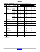
AC ELECTRICAL CHARACTERISTICS (V
CC
= 5 V, T
A
= 25°C, t
r
= t
f
= 6 ns)
Symbol Parameter Conditions Typ Guaranteed Limit Units
f
MAX
Maximum Operating Frequency 60 33 MHz
t
PHL
, t
PLH
Maximum Propagation Delay, Clock to Q C
L
= 45 pF 17 27 ns
t
PZH
, t
PZL
Maximum Output Enable Time
R
L
= 1 kW, C
L
= 45 pF
19 28 ns
t
PHZ
, t
PLZ
Maximum Output Disable Time
R
L
= 1 kW, C
L
= 5 pF
14 25 ns
t
S
Minimum Setup Time, Data to Clock 10 12 ns
t
H
Minimum Hold Time, Clock to Data −3 5 ns
t
W
Minimum Pulse Clock Width 8 15 ns