
Data Sheet


©1983 Fairchild Semiconductor Corporation www.fairchildsemi.com
MM74HC164 Rev. 1.5.0 2
MM74HC164 — 8-Bit Serial-in/Parallel-out Shift Register
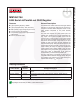
Connection Diagram
Top View
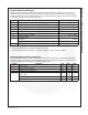
Truth Table
H
=
HIGH Level (steady state)
L
=
LOW Level (steady state)
X
=
Irrelevant (any input, including transitions)
↑
=
Transition from LOW-to-HIGH level.
Q
AO
, Q
BO
, Q
HO
=
the level of Q
A
, Q
B
, or Q
H
,
respectively, before the indicated steady state input
conditions were established.
Q
An
, Q
Gn
=
The level of Q
A
or Q
G
before the most
recent
↑
transition of the clock; indicated a one-bit shift.
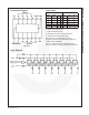
Logic Diagram
Inputs Outputs
Clear Clock A B Q
A
Q
B
... Q
H
LXXXL L
...
L
HLXXQ
AO
Q
BO
...
Q
HO
H
↑
HH H Q
An
...
Q
Gn
H
↑
LX L Q
A
...
Q
Gn
H
↑
XL L Q
An
...
Q
Gn