
Data Sheet

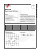


MM74HC02 — Quad 2-Input NOR Gate
© 1983 Fairchild Semiconductor Corporation www.fairchildsemi.com
MM74HC02 Rev. 1.4 4
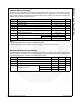
AC Electrical Characteristics
V
CC
= 5 V, T
A
= 25°C, C
L
= 15 pF, t
r
= t
f
= 6 ns
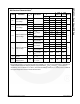
AC Electrical Characteristics
V
CC
= 2.0 V to 6.0 V, C
L
= 50 pF, t
r
= t
f
= 6 ns (unless otherwise specified)
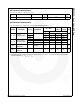
Note:
4. C
PD
determines the no load dynamic power consumption, P
D
= C
PD
V
CC
2
f + I
CC
V
CC
, and the no load dynamic
current consumption, I
S
= C
PD
V
CC
f + I
CC
.
Symbol Parameter Conditions Typ. Guaranteed Limit Unit
t
PHL
, t
PLH
Maximum Propagation Delay
815ns
Symbol Parameter V
CC
(V) Conditions
T
A
= 25°C
T
A
=-40
to 85°C
T
A
=-55
to 125°C
Unit
Typ. Guaranteed Limits
t
PHL
, t
PLH
Maximum
Propagation Delay
2.0 45 90 113 134
ns4.5 9 18 23 27
6.0 8 15 19 23
t
TLH
, t
THL
Maximum Output
Rise and Fall Time
2.0 30 75 95 110
ns4.5 8 15 19 22
6.0 7 13 16 19
C
PD
Power Dissipation
Capacitance
(4)
(per gate) 20 pF
C
IN
Maximum Input
Capacitance
5101010pF