
Data Sheet

MC1455, MC1455B, NCV1455B
http://onsemi.com
8
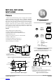
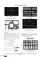
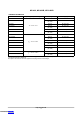
Pulse Width Modulation
If the timer is triggered with a continuous pulse train in the
monostable mode of operation, the charge time of the
capacitor can be varied by changing the control voltage at
Pin 5. In this manner, the output pulse width can be
modulated by applying a modulating signal that controls the
threshold voltage.
Figure 24. Pulse Width Modulator
+V
CC
(5.0 V to 15 V)
R
L
Output
Clock
Input
Modulation
Input
C
7
6
5
R
A
48
3
2
1
MC1455
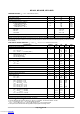
t = 0.5 ms/cm
(R
A
= 10 kW, C = 0.02 mF, V
CC
= 15 V)
Figure 25. Pulse Width Modulation Waveforms
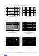
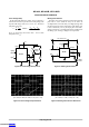
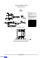
Test Sequences
Several timers can be connected to drive each other for
sequential timing. An example is shown in Figure 26 where
the sequence is started by triggering the first timer which
runs for 10 ms. The output then switches low momentarily
and starts the second timer which runs for 50 ms and so forth.
Figure 26. Sequential Timer
Load
MC1455
6
7
2
84
5
3
27 k
1
5.0 mF
Load
MC1455
9.1 k
6
7
1.0 mF
2
84
5
3
0.01 mF
27 k
1
0.001 mF
5.0 mF
MC1455
6
7
2
84
5
3
1
Load
0.001 mF
18.2 k
9.1 k
0.01 mF 0.01 mF
V
CC
(5.0 V to 15 V)
Downloaded from Arrow.com.Downloaded from Arrow.com.Downloaded from Arrow.com.Downloaded from Arrow.com.Downloaded from Arrow.com.Downloaded from Arrow.com.Downloaded from Arrow.com.Downloaded from Arrow.com.