
Data Sheet

©2002 Fairchild Semiconductor Corporation Rev. A4, October 2002
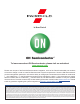
KSH41C
NPN Epitaxial Silicon Transistor
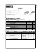
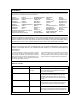
Absolute Maximum Ratings
T
C
=25°C unless otherwise noted
Electrical Characteristics
T
C
=25°C unless otherwise noted
* Pulse Test: PW≤300µs, Duty Cycle≤2%
Symbol Parameter Value Units
V
CBO
Collector-Base Voltage 100 V
V
CEO
Collector-Emitter Voltage 100 V
V
EBO
Emitter-Base Voltage 5 V
I
C
Collector Current (DC) 6 A
I
CP
Collector Current (Pulse) 10 A
I
B
Base Current 2 A
P
C
Collector Dissipation (T
C
=25°C) 20 W
Collector Dissipation (T
a
=25°C) 1.75 W
T
J
Junction Temperature 150 °C
T
STG
Storage Temperature - 65 ~ 150 °C
Symbol Parameter Test Condition Min. Max. Units
V
CEO
(sus) * Collector-Emitter Sustaining Voltage I
C
= 30mA, I
B
= 0 100 V
I
CEO
Collector Cut-off Current V
CE
= 60V, I
B
= 0 50 µA
I
CES
Collector Cut-off Current V
CE
= 100V, V
BE
= 0 10 uA
I
EBO
Emitter Cut-off Current V
BE
= 5V, I
C
= 0 0.5 mA
h
FE
* DC Current Gain V
CE
= 4V, I
C
= 0.3A
V
CE
= 4V, I
C
= 3A
30
15 75
V
CE
(sat) * Collector-Emitter Saturation Voltage I
C
= 6A, I
B
= 600mA 1.5 V
V
BE
(on) * Base-Emitter On Voltage V
CE
= 6A, I
C
= 4A 2 V
f
T
Current Gain Bandwidth Product V
CE
= 10V, I
C
= 500mA 3 MHz
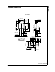
KSH41C
General Purpose Amplifier Low Speed
Switching Applications
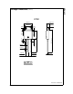
D-PAK for Surface Mount Applications
• Lead Formed for Surface Mount Application (No Suffix)
• Straight Lead (I-PAK, “- I” Suffix)
• Electrically Similar to Popular TIP41 and TIP41C
1.Base 2.Collector 3.Emitter
D-PAK I-PAK
11