
Data Sheet

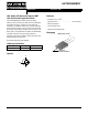


©2001 Fairchild Semiconductor Corporation HGTG20N60B3D Rev. B
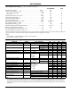
Absolute Maximum Ratings
T
C
= 25
o
C, Unless Otherwise Specified
HGTG20N60B3D UNITS
Collector to Emitter Voltage . . . . . . . . . . . . . . . . . . . . . . . . . . . . . . . . . . . . . . . . . . . . . . BV
CES
600 V
Collector to Gate Voltage, R
GE
= 1MΩ . . . . . . . . . . . . . . . . . . . . . . . . . . . . . . . . . . . . BV
CGR
600 V
Collector Current Continuous. . . . . . . . . . . . . . . . . . . . . . . . . . . . . . . . . . . . . . . . . . . . . I
C25
40 A
At T
C
= 110
o
C . . . . . . . . . . . . . . . . . . . . . . . . . . . . . . . . . . . . . . . . . . . . . . . . . . . . . . . I
C110
20 A
Average Diode Forward Current at 110
o
C. . . . . . . . . . . . . . . . . . . . . . . . . . . . . . . . . . . .I
(AVG)
20 A
Collector Current Pulsed (Note 1) . . . . . . . . . . . . . . . . . . . . . . . . . . . . . . . . . . . . . . . . . . . I
CM
160 A
Gate to Emitter Voltage Continuous. . . . . . . . . . . . . . . . . . . . . . . . . . . . . . . . . . . . . . . . . V
GES
±20 V
Gate to Emitter Voltage Pulsed . . . . . . . . . . . . . . . . . . . . . . . . . . . . . . . . . . . . . . . . . . . . V
GEM
±30 V
Switching Safe Operating Area at T
C
= 150
o
C . . . . . . . . . . . . . . . . . . . . . . . . . . . . . . . SSOA 30A at 600V
Power Dissipation Total at T
C
= 25
o
C . . . . . . . . . . . . . . . . . . . . . . . . . . . . . . . . . . . . . . . . . P
D
165 W
Power Dissipation Derating T
C
> 25
o
C . . . . . . . . . . . . . . . . . . . . . . . . . . . . . . . . . . . . . . . . . . 1.32 W/
o
C
Operating and Storage Junction Temperature Range . . . . . . . . . . . . . . . . . . . . . . . . T
J
, T
STG
-40 to 150
o
C
Maximum Lead Temperature for Soldering . . . . . . . . . . . . . . . . . . . . . . . . . . . . . . . . . . . . . T
L
260
o
C
Short Circuit Withstand Time (Note 2) at V
GE
= 15V. . . . . . . . . . . . . . . . . . . . . . . . . . . . . .t
SC
4 µs
Short Circuit Withstand Time (Note 2) at V
GE
= 10V. . . . . . . . . . . . . . . . . . . . . . . . . . . . . t
SC
10 µs
CAUTION: Stresses above those listed in “Absolute Maximum Ratings” may cause permanent damage to the device. This is a stress only rating and operation of the
device at these or any other conditions above those indicated in the operational sections of this specification is not implied.
NOTES:
1. Repetitive Rating: Pulse width limited by maximum junction temperature.
2. V
CE
= 360V, T
C
= 125
o
C, R
G
= 25Ω.
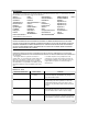
Electrical Specifications
T
C
= 25
o
C, Unless Otherwise Specified
PARAMETER SYMBOL TEST CONDITIONS MIN TYP MAX UNITS
Collector to Emitter Breakdown Voltage BV
CES
I
C
= 250µA, V
GE
= 0V 600 - - V
Collector to Emitter Leakage Current I
CES
V
CE
= BV
CES
T
C
= 25
o
C - - 250 µA
T
C
= 150
o
C--2.0mA
Collector to Emitter Saturation Voltage V
CE(SAT)
I
C
= I
C110
,
V
GE
= 15V
T
C
= 25
o
C-1.82.0V
T
C
= 150
o
C-2.12.5V
Gate to Emitter Threshold Voltage V
GE(TH)
I
C
= 250µA, V
CE
= V
GE
3.0 5.0 6.0 V
Gate to Emitter Leakage Current I
GES
V
GE
= ±20V - - ±100 nA
Switching SOA SSOA T
C
= 150
o
C
V
GE
= 15V,
R
G
= 10Ω,
L = 45µH
V
CE
= 480V 100 - - A
V
CE
= 600V 30 - - A
Gate to Emitter Plateau Voltage V
GEP
I
C
= I
C110
, V
CE
= 0.5 BV
CES
-8.0- V
On-State Gate Charge Q
G(ON)
I
C
= I
C110
,
V
CE
= 0.5 BV
CES
V
GE
= 15V - 80 105 nC
V
GE
= 20V - 105 135 nC
Current Turn-On Delay Time t
d(ON)I
T
C
= 150
o
C,
I
CE
= I
C110
V
CE
= 0.8 BV
CES,
V
GE
= 15V
R
G
= 10Ω,
L = 100µH
-25-ns
Current Rise Time t
rI
-20-ns
Current Turn-Off Delay Time t
d(OFF)I
- 220 275 ns
Current Fall Time t
fI
- 140 175 ns
Turn-On Energy E
ON
- 475 - µJ
Turn-Off Energy (Note 3) E
OFF
- 1050 - µJ
Diode Forward Voltage V
EC
I
EC
= 20A - 1.5 1.9 V
Diode Reverse Recovery Time t
rr
I
EC
= 20A, dI
EC
/dt = 100A/µs--55ns
I
EC
= 1A, dI
EC
/dt = 100A/µs--45ns
Thermal Resistance R
θJC
IGBT - - 0.76
o
C/W
Diode - - 1.2
o
C/W
NOTE:
3. Turn-Off Energy Loss (E
OFF
) is defined as the integral of the instantaneous power loss starting at the trailing edge of the input pulse and ending
at the point where the collector current equals zero (I
CE
= 0A) The HGTG20N60B3D was tested per JEDEC standard No. 24-1 Method for
Measurement of Power Device Turn-Off Switching Loss. This test method produces the true total Turn-Off Energy Loss. Turn-On losses include
diode losses.
HGTG20N60B3D