
Data Sheet


©2005 Fairchild Semiconductor Corporation www.fairchildsemi.com
6N138, 5N139, NCPL2730, HCPL2731 Rev. 1.0.5 5
Single-Channel: 6N138, 6N139 Dual-Channel: HCPL2730, HCPL2731 — Low Input Current High Gain Split Darlington Optocouplers
Electrical Characteristics (Continued) (T
A
= 0 to 70°C unless otherwise specified)
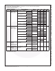
Isolation Characteristics
*All Typicals at T
A
= 25°C
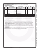
Notes:
1. Current Transfer Ratio is defined as a ratio of output collector current, I
O
, to the forward LED input current,
I
F
, times 100%.
2. Pin 7 open. (6N138 and 6N139 only)
3. Common mode transient immunity in logic HIGH level is the maximum tolerable (positive) dV
cm
/dt on the
leading edge of the common mode pulse signal V
CM
, to assure that the output will remain in a logic HIGH state
(i.e., V
O
> 2.0V). Common mode transient immunity in logic LOW level is the maximum tolerable (negative)
dV
cm
/dt on the trailing edge of the
common mode pulse signal, V
CM
, to assure that the output will remain in a logic LOW state (i.e., V
O
< 0.8V).
4. Device is considered a two terminal device: Pins 1, 2, 3 and 4 are shorted together and Pins 5, 6, 7 and 8 are
shorted together.
5. For dual channel devices, C
I-O
is measured by shorting pins 1 and 2 or pins 3 and 4 together and pins 5 through 8
shorted together.
6. Measured between pins 1 and 2 shorted together, and pins 3 and 4 shorted together.
I
Symbol Characteristics Test Conditions Min. Typ.* Max. Unit
I
I-O
Input-Output Insulation Leakage
Current
(4)
Relative humidity = 45%,T
A
= 25°C,
t = 5s, V
I-O
= 3000VDC
1.0 µA
V
ISO
Withstand Insulation Test
Voltage
(4)
RH ≤ 50%, T
A
= 25°C, I
I-O
≤ 2µA,
t = 1 min.
2500 V
RMS
R
I-O
Resistance (Input to Output)
(4)
V
I-O
= 500VDC 10
12
Ω
C
I-O
Capacitance (Input to Output)
(4)(5)
f = 1MHz 0.6 pF
I
I-I
Input-Input Insulation Leakage
Current
(6)
RH ≤ 45%, V
I-I
= 500VDC, t = 5s,
HCPL2730/2731 only
0.005 µA
R
I-I
Input-Input Resistance
(6)
V
I-I
= 500VDC, HCPL2730/2731 only 10
11
Ω
C
I-I
Input-Input Capacitance
(6)
f = 1MHz, HCPL2730/2731 only 0.03 pF