
Data Sheet

© 2007 Fairchild Semiconductor Corporation www.fairchildsemi.com
FSQ0365, FSQ0265, FSQ0165, FSQ321 • Rev. 1.0.6 14
FSQ0365/0265/0165/321 — Green Mode Fairchild Power Switch (FPS™) for Valley Switching Converter
4.3 Over-Voltage Protection (OVP): If the secondary-
side feedback circuit malfunctions or a solder defect
causes an opening in the feedback path, the current
through the opto-coupler transistor becomes almost
zero. Then V
FB
climbs up in a similar manner to the
overload situation, forcing the preset maximum current
to be supplied to the SMPS until the overload protection
triggers. Because more energy than required is provided
to the output, the output voltage may exceed the rated
voltage before the overload protection triggers, resulting
in the breakdown of the devices in the secondary side.
To prevent this situation, an OVP circuit is employed. In
general, the peak voltage of the sync signal is
proportional to the output voltage and the FSQ-series
uses a sync signal instead of directly monitoring the
output voltage. If the sync signal exceeds 6V, an OVP is
triggered, shutting down the SMPS. To avoid undesired
triggering of OVP during normal operation, the peak
voltage of the sync signal should be designed below 6V.
4.4 Thermal Shutdown (TSD): The SenseFET and the
control IC are built in one package. This makes it easy
for the control IC to detect the abnormal over
temperature of the SenseFET. If the temperature
exceeds ~150°C, the thermal shutdown triggers.
5. Soft-Start: An internal soft-start circuit increases
PWM comparator inverting input voltage with the
SenseFET current slowly after it starts up. The typical
soft-start time is 15ms. The pulsewidth to the power
switching device is progressively increased to establish
the correct working conditions for transformers,
inductors, and capacitors. The voltage on the output
capacitors is progressively increased with the intention
of smoothly establishing the required output voltage.
This helps prevent transformer saturation and reduces
stress on the secondary diode during startup.
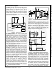
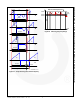
6. Burst Operation: To minimize power dissipation in
Standby Mode, the FPS enters Burst-Mode operation.
As the load decreases, the feedback voltage decreases.
As shown in Figure 26, the device automatically enters
Burst Mode when the feedback voltage drops below
V
BURL
(350mV). At this point, switching stops and the
output voltages start to drop at a rate dependent on
standby current load. This causes the feedback voltage
to rise. Once it passes V
BURH
(550mV), switching
resumes. The feedback voltage then falls and the
process repeats. Burst Mode alternately enables and
disables switching of the power SenseFET, reducing
switching loss in Standby Mode.
V
FB
V
DS
0.35V
0.55V
I
DS
V
O
V
O
set
time
Switching
disabled
t1
t2 t3
Switching
disabled
t4
FSQ0365RN Rev.00
Figure 26. Waveforms of Burst Operation
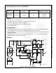
7. Switching Frequency Limit
: To minimize switching
loss and Electromagnetic Interference (EMI), the
MOSFET turns on when the drain voltage reaches its
minimum value in valley switching operation. However,
this causes switching frequency to increases at light
load conditions. As the load decreases, the peak drain
current diminishes and the switching frequency
increases. This results in severe switching losses at
light-load condition, as well as intermittent switching and
audible noise. Because of these problems, the valley
switching converter topology has limitations in a wide
range of applications.
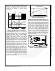
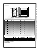
To overcome this problem, FSQ-series employs a
frequency-limit function, as shown in Figure 27 and
Figure 28. Once the SenseFET is turned on, the next
turn-on is prohibited during the blanking time (t
B
). After
the blanking time, the controller finds the valley within
the detection time window (t
W
) and turns on the
MOSFET, as shown in Figure 27 and Figure 28 (cases
A, B, and C). If no valley is found during t
W
, the internal
SenseFET is forced to turn on at the end of t
W
(case D).
Therefore, FSQ devices have a minimum switching
frequency of 55kHz and a maximum switching frequency
of 67kHz, as shown in Figure 28.