
Data Sheet


© 2011 Fairchild Semiconductor Corporation www.fairchildsemi.com
FSL206MR • Rev. 1.0.5 11
FSL206MR — Green Mode Fairchild Power Switch (FPS™)
Line Under-Voltage Protection (LUVP)
If the input voltage of the converter is lower than the
minimum operating voltage, the converter input current
increases too much, causing components failure. If the
input voltage is low, the converter should be protected.
In the FSL206MR, the LUVP circuit senses the input
voltage using the LS pin and, if this voltage is lower than
1.5V, the LUVP signal is generated. The comparator
has 0.5V hysteresis. If the LUVP signal is generated, the
output drive block is shut down and the output voltage
feedback loop is saturated.
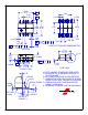
Figure 21. Line UVP Circuit
Soft-Start
The FSL206MR has an internal soft-start circuit that
slowly increases the feedback voltage, together with the
SenseFET current, after it starts. The typical soft-start
time is 15ms, as shown in Figure 22, where progressive
increments of the SenseFET current are allowed during
the startup phase. The pulse width to the power
switching device is progressively increased to establish
the correct working conditions for transformers,
inductors, and capacitors. The voltage on the output
capacitors is progressively increased with the intention
of smoothly establishing the required output voltage. It
also helps prevent transformer saturation and reduce
the stress on the secondary diode.
Figure 22. Internal Soft-Start
Burst Operation
To minimize power dissipation in Standby Mode, the
FPS enters Burst Mode. As the load decreases, the
feedback voltage decreases. As shown in Figure 23, the
device automatically enters Burst Mode when the
feedback voltage drops below V
BURH
. Switching
continues until the feedback voltage drops below V
BURL
.
At this point, switching stops and the output voltages
start to drop at a rate dependent on the standby current
load. This causes the feedback voltage to rise. Once it
passes V
BURH
, switching resumes. The feedback voltage
then falls and the process repeats. Burst Mode
alternately enables and disables switching of the
SenseFET and reduces switching loss in Standby Mode.
V
FB
V
DS
V
BURL
V
BURH
I
DS
V
O
Vo
set
time
Switching
disabled
t1 t2 t3
Switching
disabled
t4
Figure 23. Burst-Mode Operation