
Data Sheet


© 2009 Fairchild Semiconductor Corporation www.fairchildsemi.com
FSGM0765R • Rev. 1.0.2 3
FSGM0765R — Green-Mode Fairchild Power Switch (FPS™)
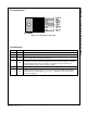
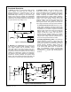
Pin Configuration
Figure 3. Pin Configuration (Top View)
Pin Definitions
Pin # Name Description
1 Drain SenseFET Drain. High-voltage power SenseFET drain connection.
2 GND Ground. This pin is the control ground and the SenseFET source.
3 V
CC
Power Supply. This pin is the positive supply input, which provides the internal operating
current for both startup and steady-state operation.
4 FB
Feedback. This pin is internally connected to the inverting input of the PWM comparator.
The collector of an opto-coupler is typically tied to this pin. For stable operation, a capacitor
should be placed between this pin and GND. If the voltage of this pin reaches 6V, the
overload protection triggers, which shuts down the FPS.
5 N.C. No Connection.
6 V
STR
Startup. This pin is connected directly, or through a resistor, to the high-voltage DC link.
At startup, the internal high-voltage current source supplies internal bias and charges the
external capacitor connected to the V
CC
pin. Once V
CC
reaches 12V, the internal current
source (I
CH
) is disabled.