
Data Sheet

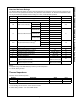

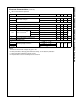


Electrical Characteristics (Continued)
T
A
= 25°C unless otherwise specified.
Notes:
9. Pulse test: Pulse width ≤ 300µS, duty cycle ≤ 2%.
10. These parameters, although guaranteed at the design, are not tested in production.
11. These parameters indicate the inductor current.
12. This parameter is the current flowing into the control IC.
Symbol Parameter Condition Min. Typ. Max. Unit
BURST MODE SECTION
V
BURH
Burst Mode Voltages
V
CC
= 14V 0.7 V
V
BURL
V
CC
= 14V 0.5 V
PROTECTION SECTION
V
SD
Shutdown Feedback Voltage V
FB
≥ 5.5V 5.5 6.0 6.5 V
I
DELAY
Shutdown Delay Current V
FB
= 5V 2.8 3.5 4.2 µA
t
LEB
Leading-Edge Blanking Time 250 ns
I
LIMIT
Peak Current Limit
(11)
FSDM0465RE V
FB
= 5V, V
CC
= 14V 1.60 1.80 2.00
AFSDM0565RE V
FB
= 5V, V
CC
= 14V 2.00 2.25 2.50
FSDM07652RE V
FB
= 5V, V
CC
= 14V 2.20 2.50 2.70
V
OVP
Over-Voltage Protection 18 19 20 V
T
SD
Thermal Shutdown Temperature
(10)
130 145 160 °C
TOTAL DEVICE SECTION
I
OP
Operating Supply Current
(12)
V
FB
= GND, V
CC
= 14V
2.5 5.0 mAI
OP(MIN)
V
FB
= GND, V
CC
= 10V
I
OP(MAX)
V
FB
= GND, V
CC
= 18V
www.onsemi.com
7
FSDM0465RE, FSDM0565RE, FSDM07652RE — Green Mode Power Switch