
Data Sheet


FSDM0465RE, FSDM0565RE, FSDM07652RE — Green Mode Power Switch
Pin Configuration
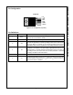
Figure 3. Pin Configuration (Top View)
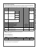
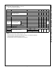
Pin Definitions
Pin # Name Description
1Drain
SenseFET drain. This pin is the high-voltage power SenseFET drain. It is de-
signed to drive the transformer directly.
2GNDGround. This pin is the control ground and the SenseFET source.
3V
CC
Power Supply. This pin is the positive supply voltage input. During start-up,
the power is supplied by an internal high-voltage current source connected to
the V
str
pin. When V
CC
reaches 12V, the internal high-voltage current source
is disabled and the power is supplied from the auxiliary transformer winding.
4FB
Feedback. This pin is internally connected to the inverting input of the PWM
comparator. The collector of an opto-coupler is typically tied to this pin. For
stable operation, a capacitor should be placed between this pin and GND. If
the voltage of this pin reaches 6.0V, the overload protection is activated,
re-sulting in shutdown of the Power Switch.
5 NC No Connection.
6V
str
Start-up. This pin is connected directly to the high-voltage DC link. At start-up,
the internal high-voltage current source supplies internal bias and charges the
external capacitor connected to the V
CC
pin. Once V
CC
reaches 12V, the in-
ternal current source is disabled.
6. V
str
5. NC
4. FB
3. V
CC
2. GND
1. Drain
TO-220F-6L
www.onsemi.com
4