
Data Sheet


FSBB15CH60C Motion SPM® 3 Series
10 www.fairchildsemi.com©2008 Fairchild Semiconductor Corporation
FSBB15CH60C Rev. 1.6
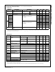
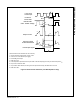
Time Charts of Protective Function
Input Signal
Output Current
Fault Output Signal
Control
Supply Voltage
RESET
UV
CCR
Protection
Circuit State
SET RESET
UV
CCD
a1
a3
a2
a4
a6
a5
a7
a1 : Control supply voltage rises: after the voltage rises UV
CCR
, the circuits start to operate when next input is applied.
a2 : Normal operation: IGBT ON and carrying current.
a3 : Under-voltage detection (UV
CCD
).
a4 : IGBT OFF in spite of control input condition.
a5 : Fault output operation starts.
a6 : Under-voltage reset (UV
CCR
).
a7 : Normal operation: IGBT ON and carrying current.
Figure 8. Under-Voltage Protection (Low-Side)
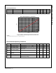
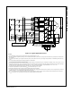
Input Signal
Output Current
Fault Output Signal
Control
Supply Voltage
RESET
UV
BSR
Protection
Circuit State
SET RESET
UV
BSD
b1
b3
b2
b4
b6
b5
High-level (no fault output)
b1 : Control supply voltage rises: after the voltage reaches UV
BSR
, the circuits start to operate when next input is applied.
b2 : Normal operation: IGBT ON and carrying current.
b3 : Under-voltage detection (UV
BSD
).
b4 : IGBT OFF in spite of control input condition, but there is
no fault output signal.
b5 : Under-voltage reset (UV
BSR
).
b6 : Normal operation: IGBT ON and carrying current.
Figure 9. Under-Voltage Protection (High-Side)